Art Design|Vacuum Flourescent Display

Merging engineering and art has always been my dream. Using my engineering experience in robot design and manufacturing, I designed a clock that was displayed using a vacuum fluorescent display(VFD)tube

What is VFD?
VFD (Vacuum Fluorescent Display) is a display device developed from a vacuum tube, and its basic characteristics are basically the same as the working characteristics of the tube. It consists of a cathode that emits electrons (direct heat, collectively referred to as filament), a gate that accelerates the flow of electrons, an anode on a glass substrate printed with electrodes and phosphors, and a grid and a glass cover. It uses electrons to hit the phosphor to make the phosphor emit light, which is a self-luminescent display device.
Why VFD?
VFD uses electrons to hit the phosphor to make the phosphor emit light, which is a self-emitting display device. Compared with LED and LCD, because it can do multi-color display, high brightness, not affected by the surrounding environment, even at night, it also emits bright brilliance. The life of VFD is more than 30,000 hours of continuous working life, that is, it can continue to work for more than ten years, which is almost twice the life of LCD and LED. VFD fluorescent display, VFD fluorescent display due to its high brightness, multi-color, long life, anti-interference, high brightness and other characteristics are widely used in all kinds of home appliances, weighing instruments, electronic instrumentation, military and many other fields.
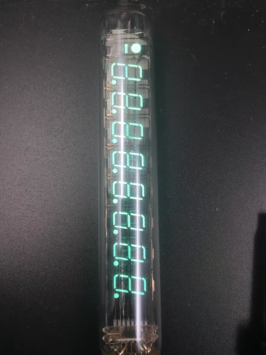
IV-18 VFD
IV-18 (ИВ-18) fluorescent electronic digital tube, a product of the former Soviet Union in the 80-90s of the last century, which was mass-manufactured and used in military equipment during the Cold War; After the end of the cold war, along with other vast remnants of war, they were buried underground or mothballed in the corners of cold warehouses……
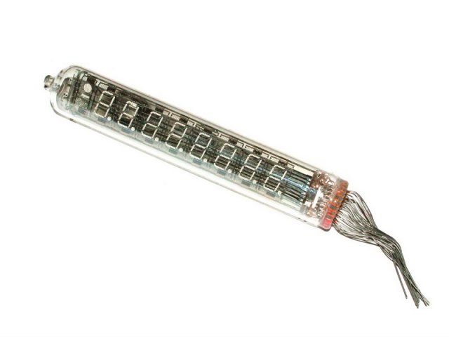
ИВ-18
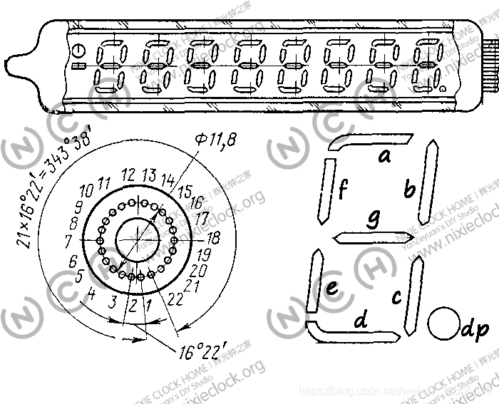
Unlike the Chinese YS-13/18 and the Soviet Union’s IV-11, she has eight 7-segment numbers embedded in one tube, and each number has a decimal point in the lower right corner, and on the left side of the tube, there is a short horizontal line representing negative numbers, and a large dot symbol above the short dash.
Below is the original instruction manual in Russian
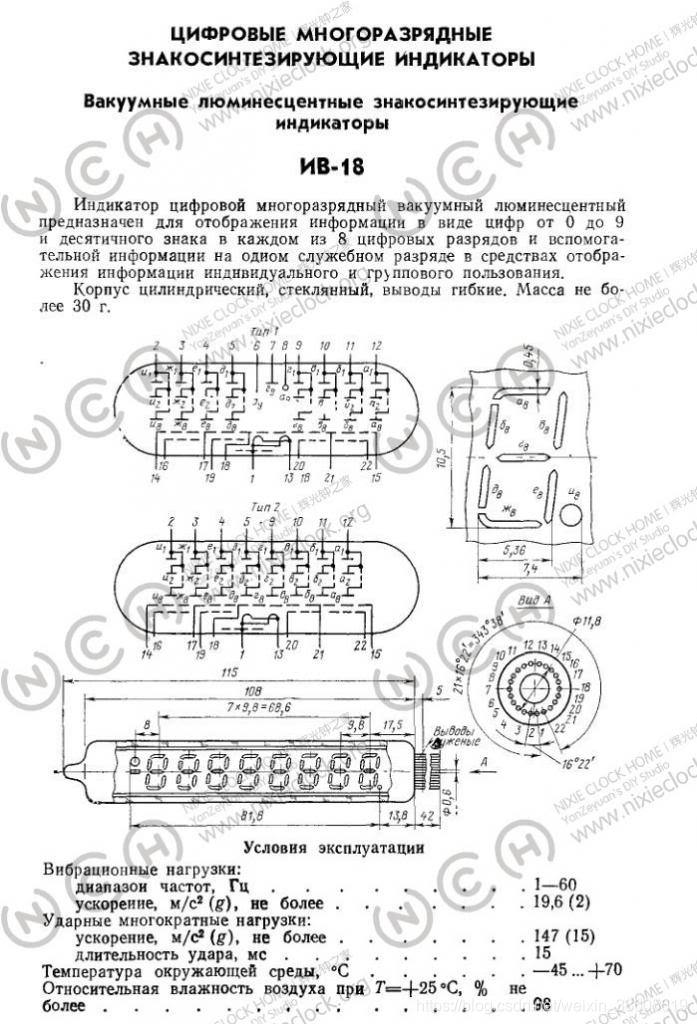
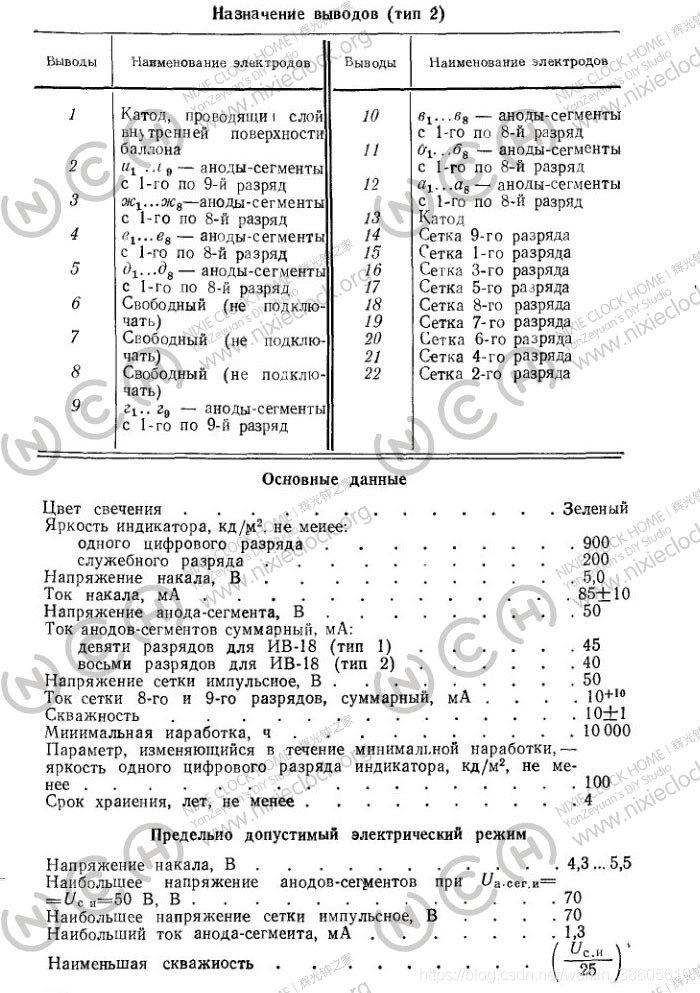
The main parameters are as follows
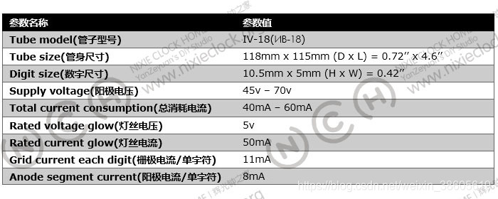
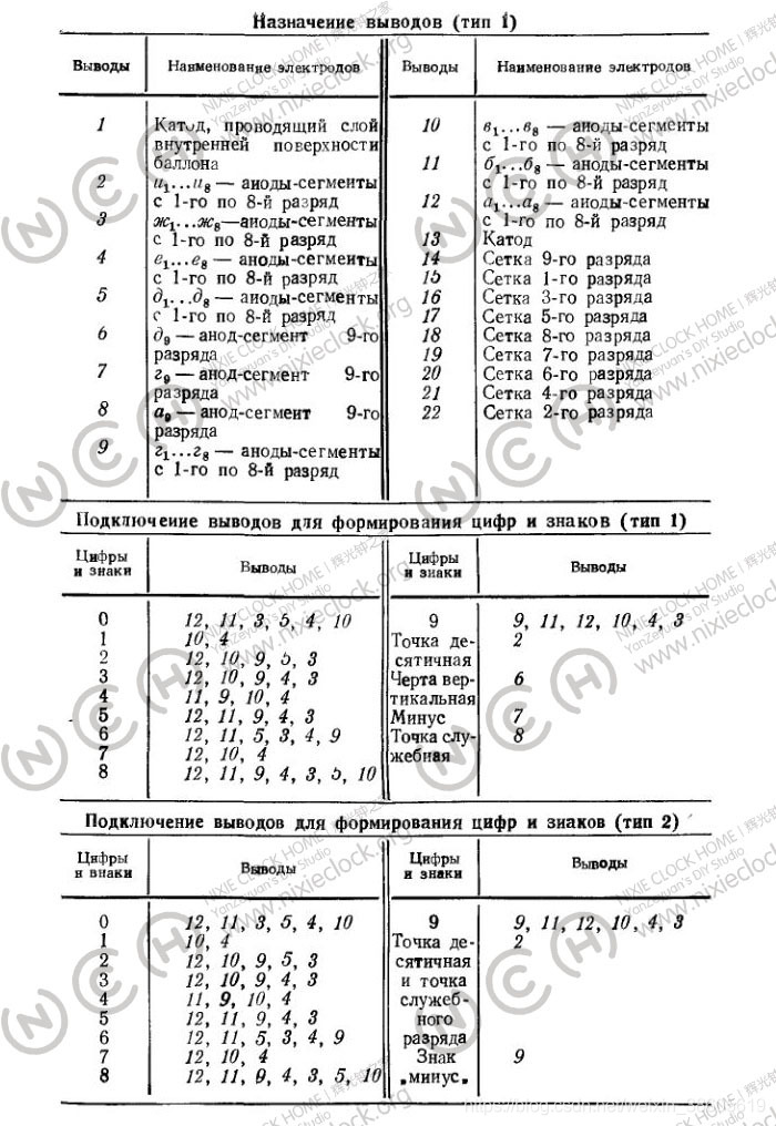
IV-18 fluorescent tube has a total of 22 pins, of which 3 pins do not have any connection, the actual use of 19 pins, the pin definition is shown in the figure below:
Design and Manufacture
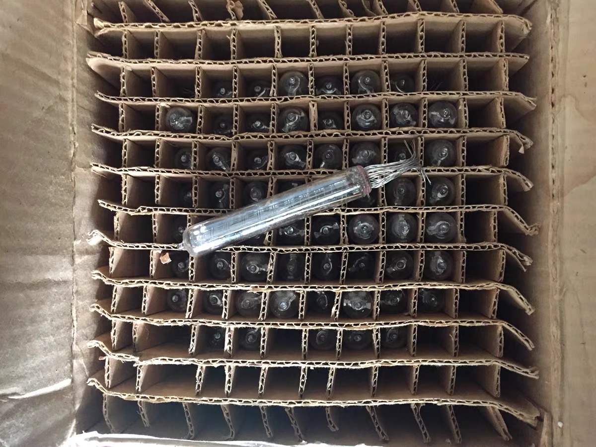
I was lucky enough to buy a Soviet IV-18 VFD from the 1980s on the second-hand market, so I wanted to look up information and use this VFD to make a clock
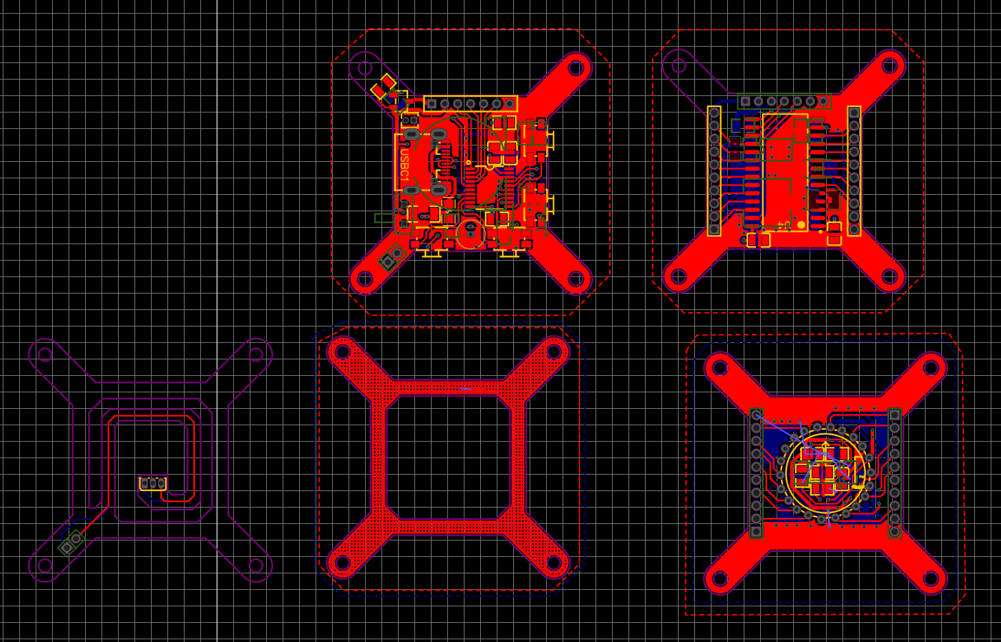
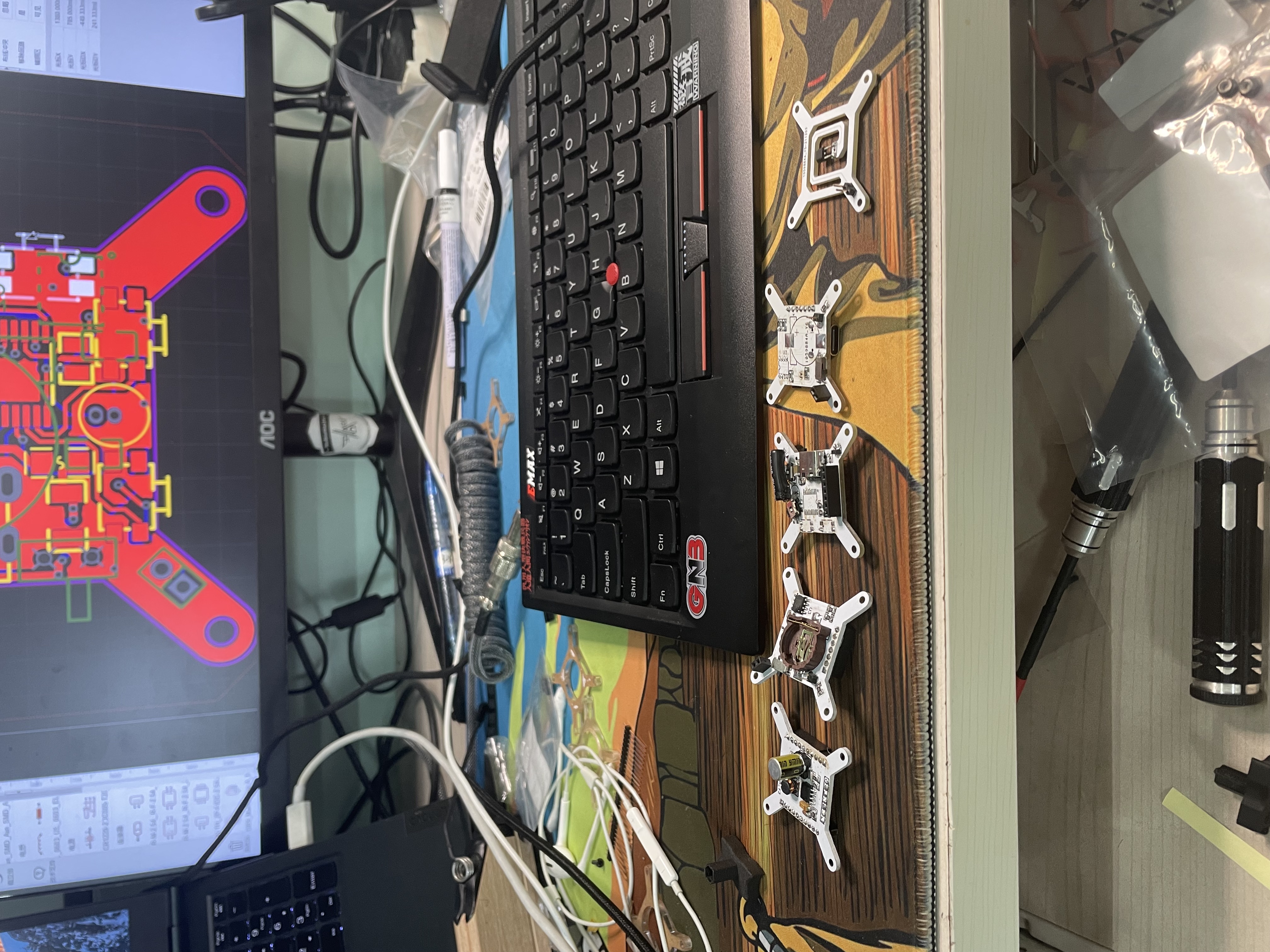
The circuit design is not complicated, there is almost no technical content, and it is a very simple typical application. And I do not have the mentality of urging hair to seek faults, only hope that the entire circuit runs stably and reliably, the PCB layout is reasonable, and the number of devices is as few as possible; The whole circuit is composed of a boost circuit, MCU main control, RTC module, VFD driver, peripheral and interface devices.I designed the VFD driver circuit using LCEDA, an online EDA tool in China and buy BOM components on JLC.
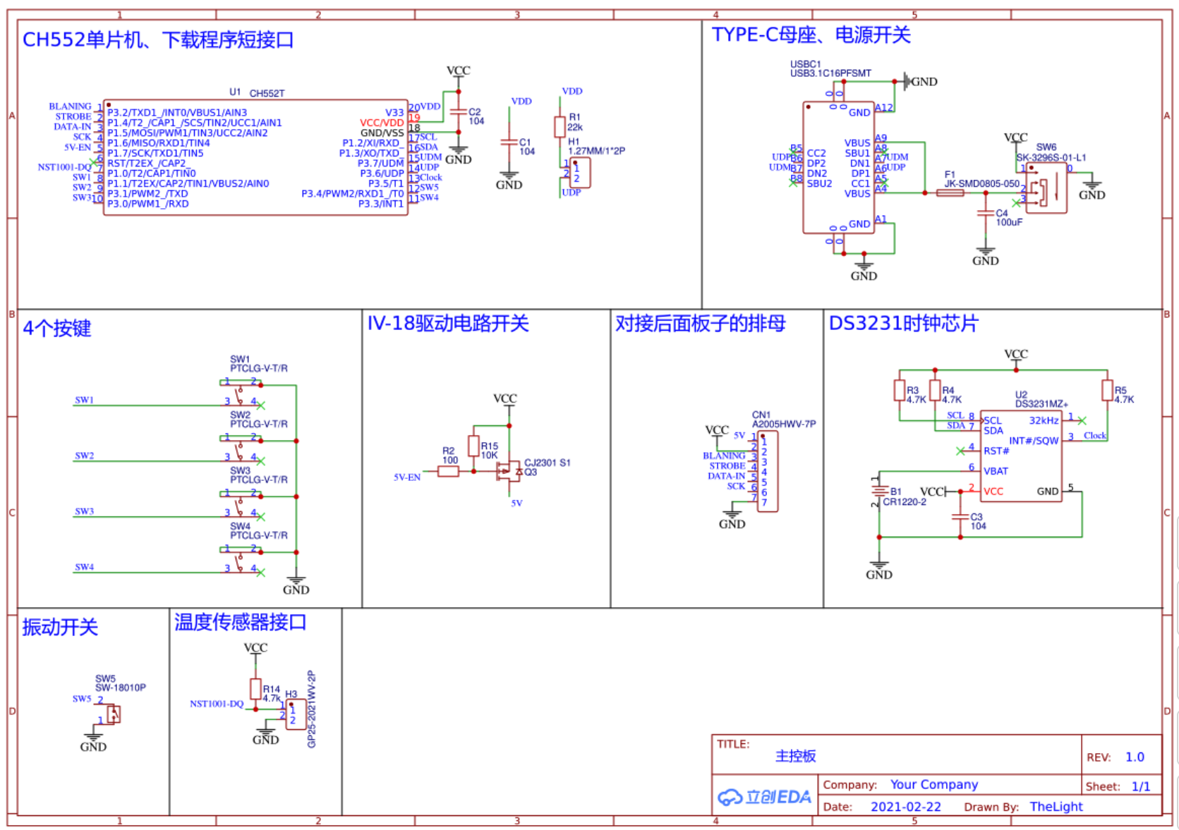
The boost circuit part uses the cheap and classic MC34063 for high-voltage boosting, and the MOS tube IRLR024 is expanded, and the boost efficiency is greatly improved, and the MC34063, inductor, and MOS tube do not feel the temperature at all; The recommended operating voltage of the IV-18 is 45v-70v, and it has been tested to work best at 49v.
The RTC module still adopts the DS3231SN high-precision clock chip with built-in temperature compensated crystal oscillator, and is equipped with CR1220 lithium battery, which can ensure that the power is turned on within 3 years without re-alignment;
The DS3231SN does not introduce much, the 400k high-speed IIC interface provides ±2ppm output accuracy over the 0°C to 40°C operating temperature range;
The fluorescent tube driver chip selected this time is Maxim’s VFD special driver chip MAX6921, which has 20 output ports, just to meet the needs of IV-18 fluorescent tubes, segment and bit selective output voltage can be as high as 76V, only a few capacitors in the peripheral area, no other devices, and only 4 communication lines are connected to the MCU for serial communication control.
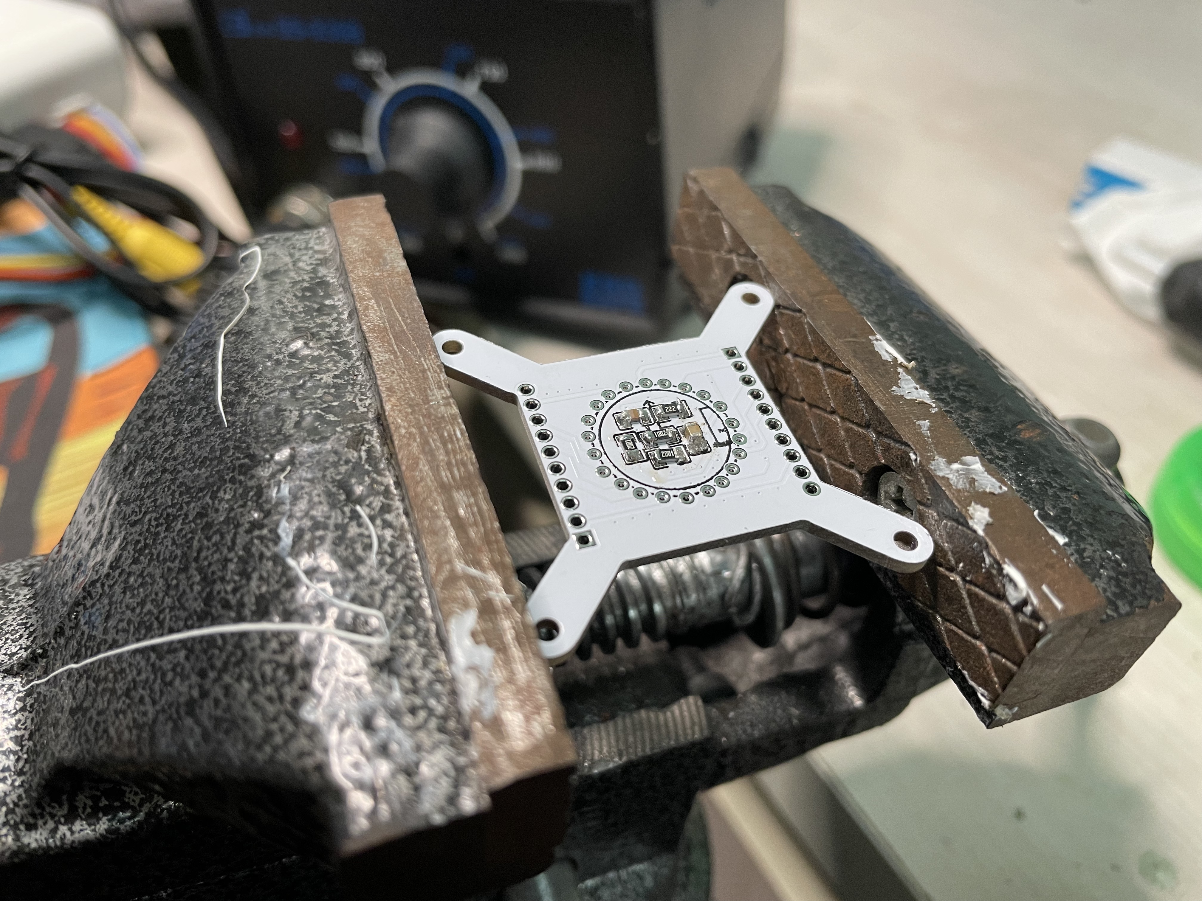
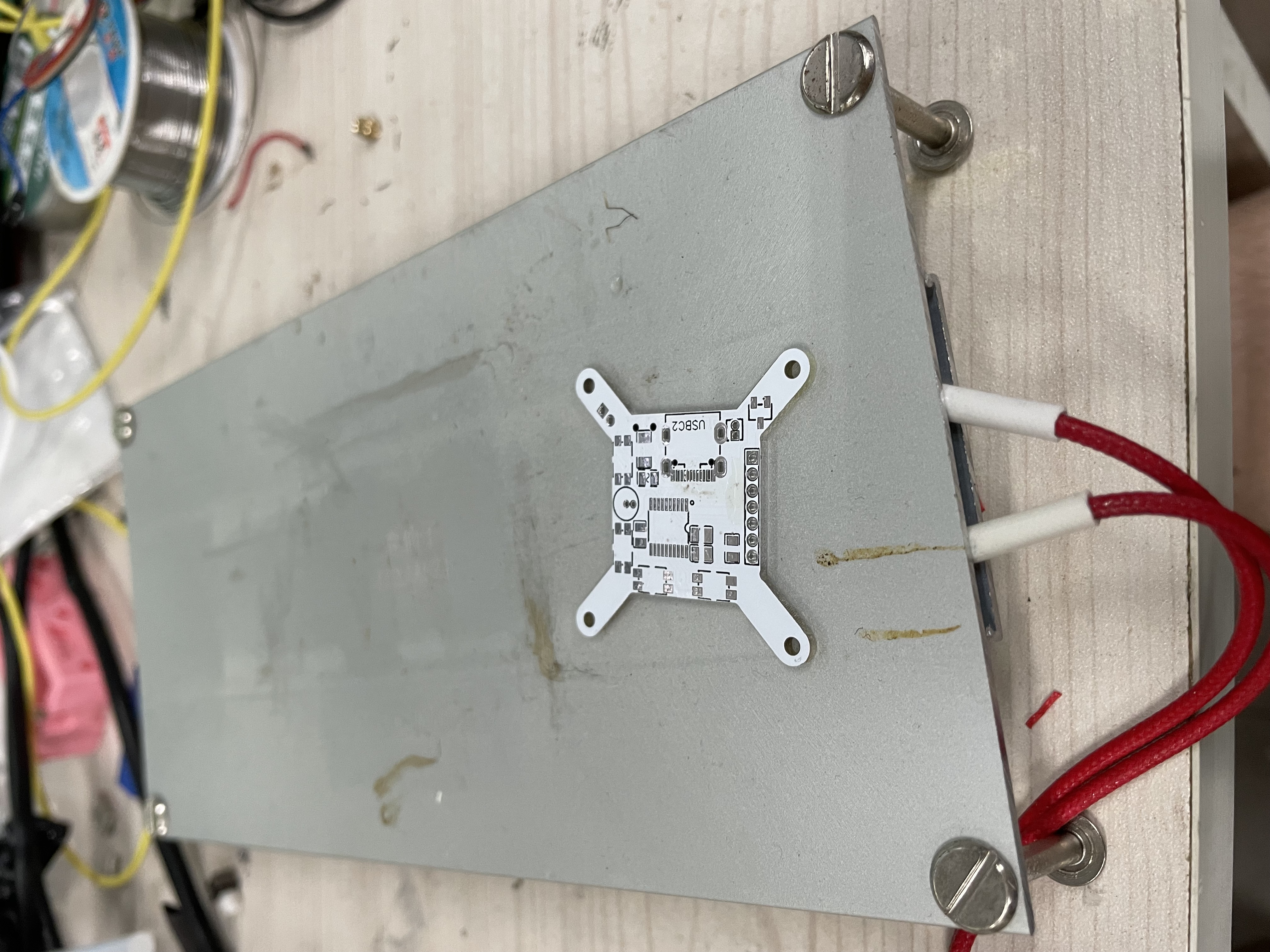
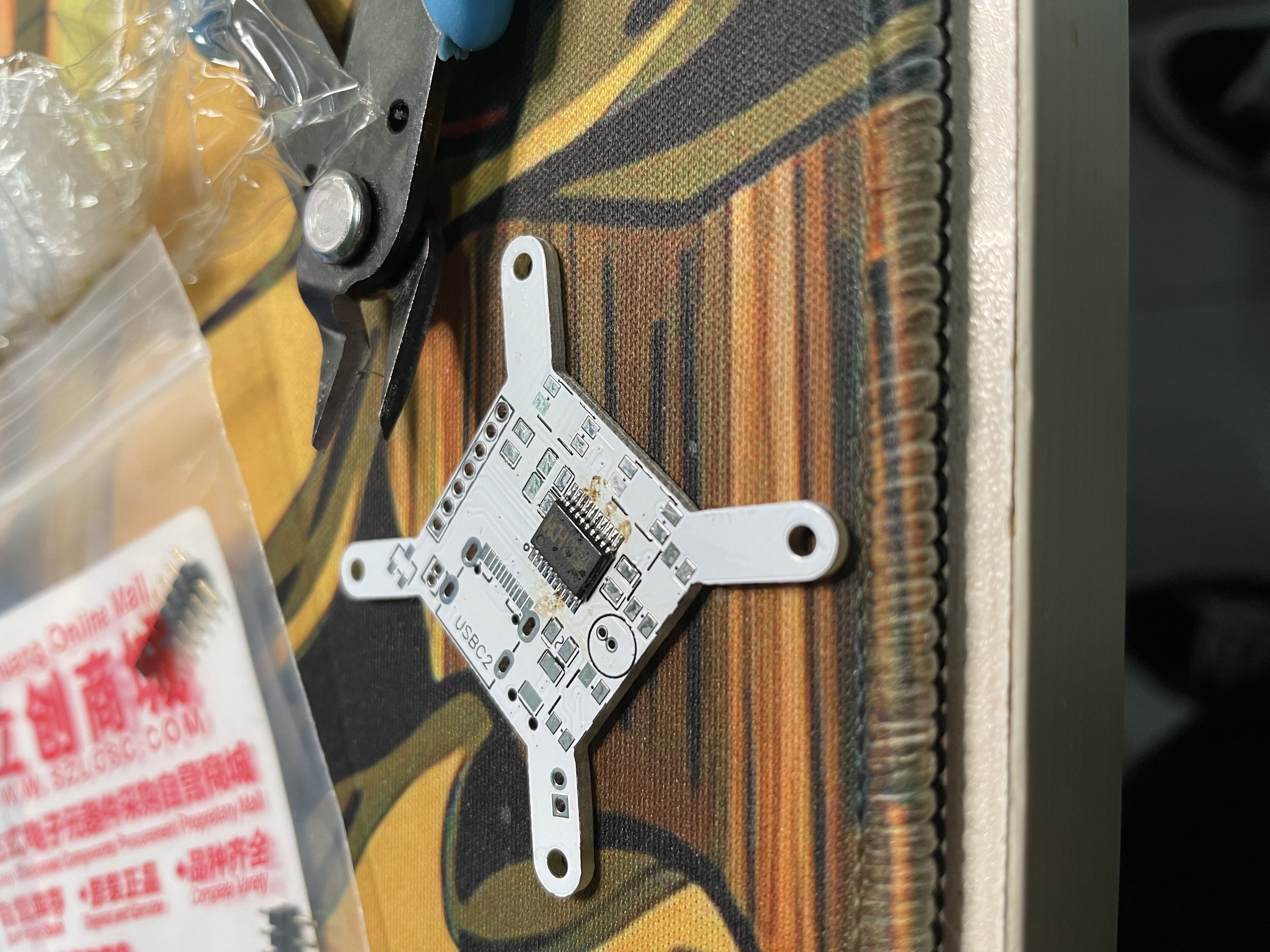
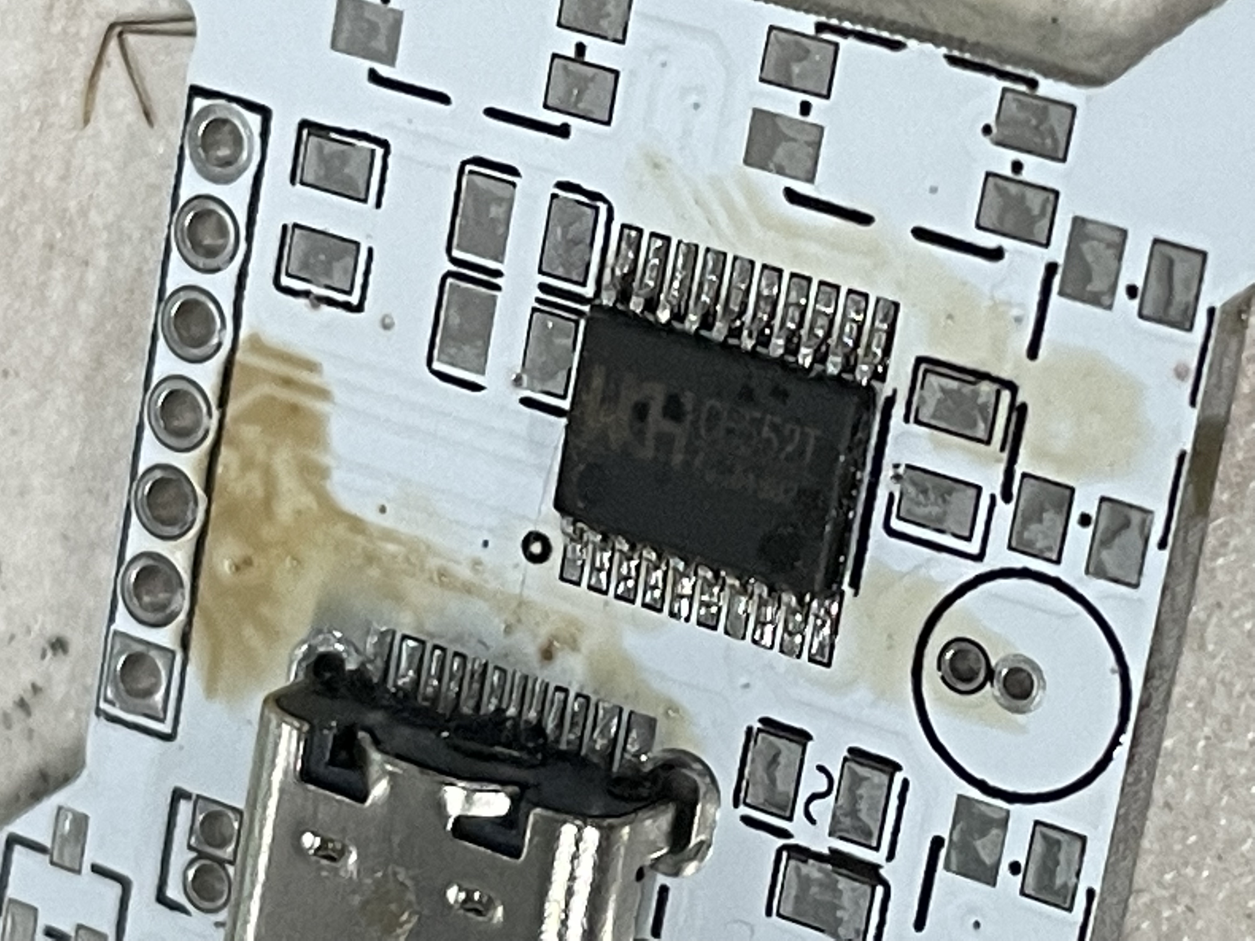
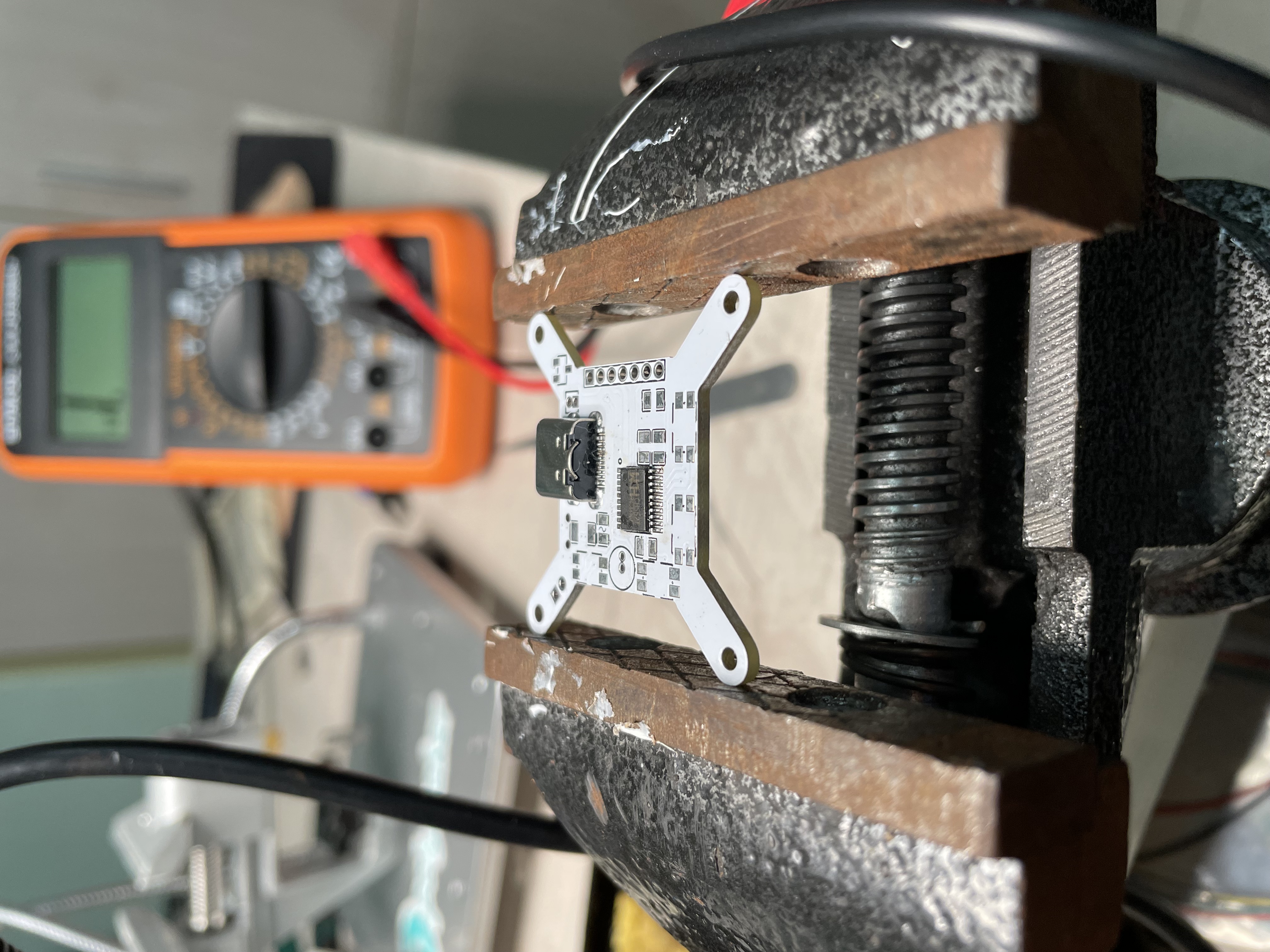
Soldering electronic components
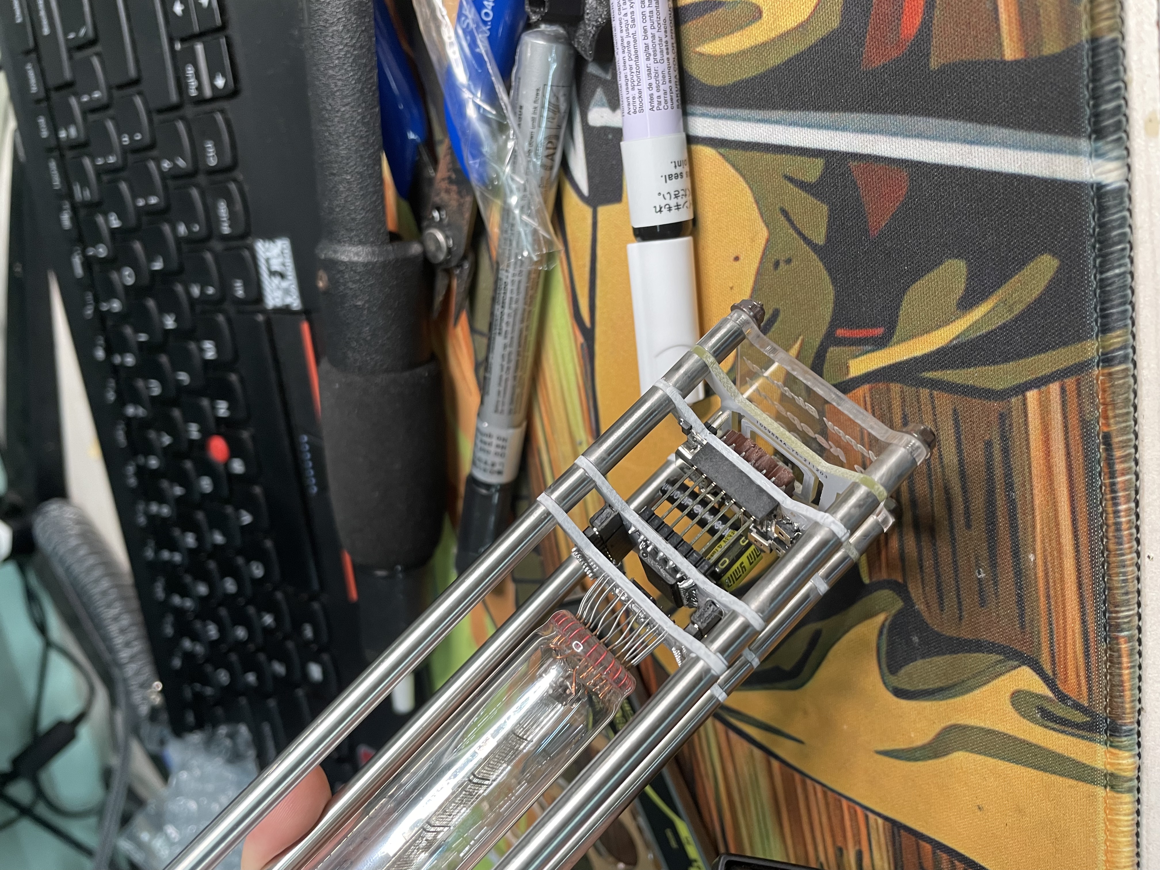
I solder the damaged circuit board during debugging
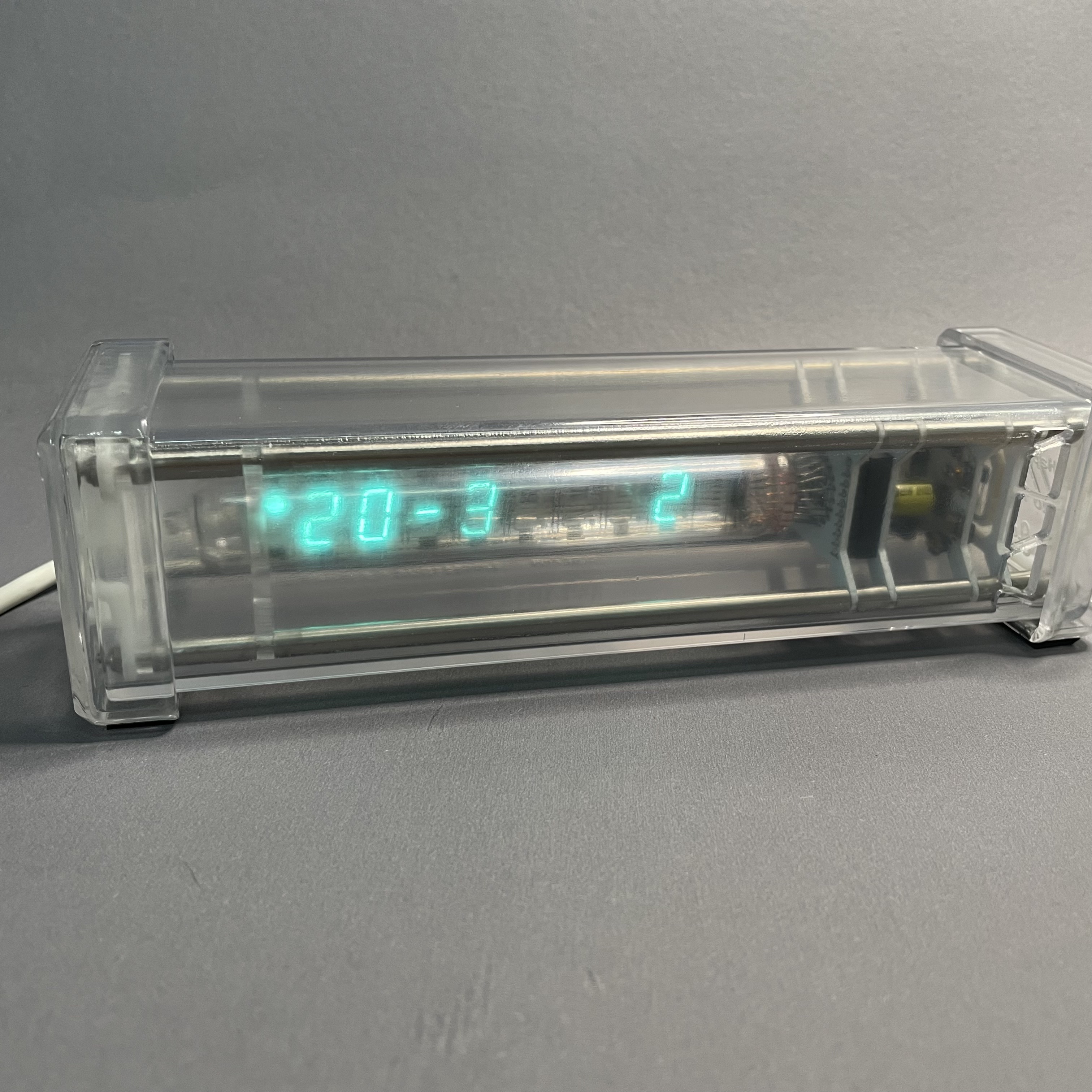
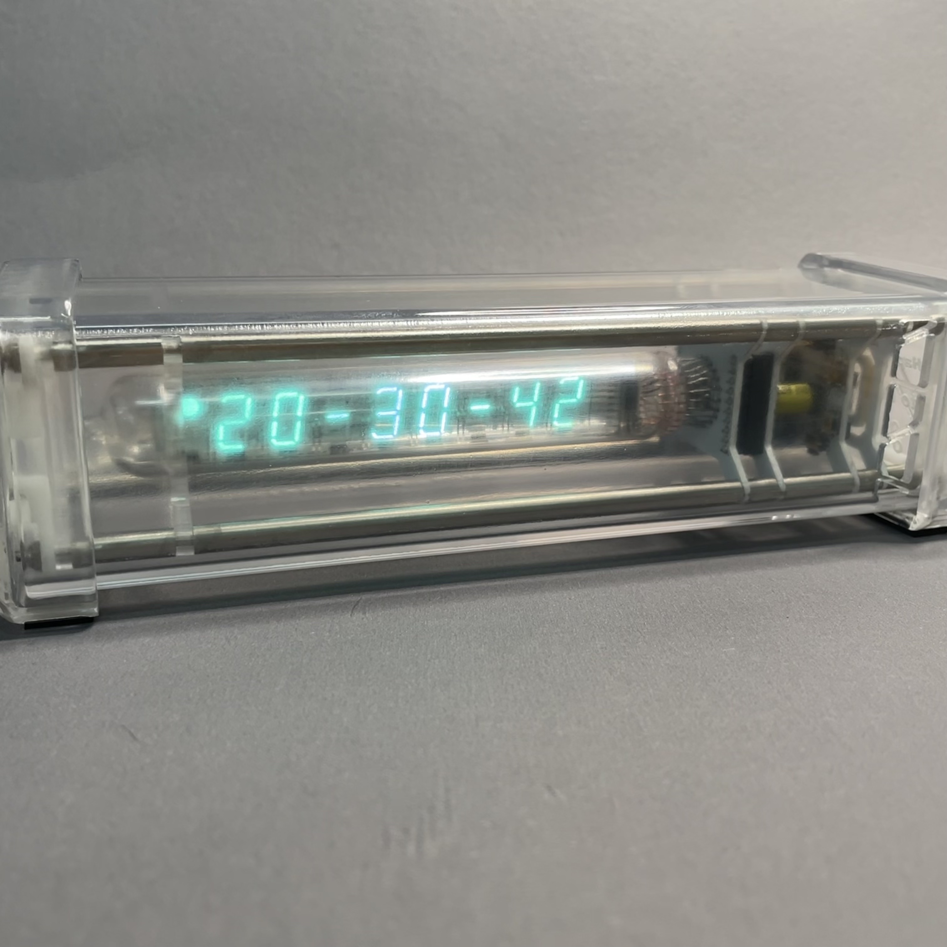
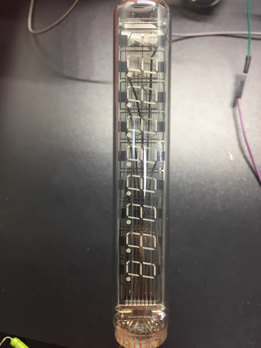
After a week of manual soldering and commissioning, the VFD finally displayed properly. I ported a set of clock microcontroller programs to implement the clock function
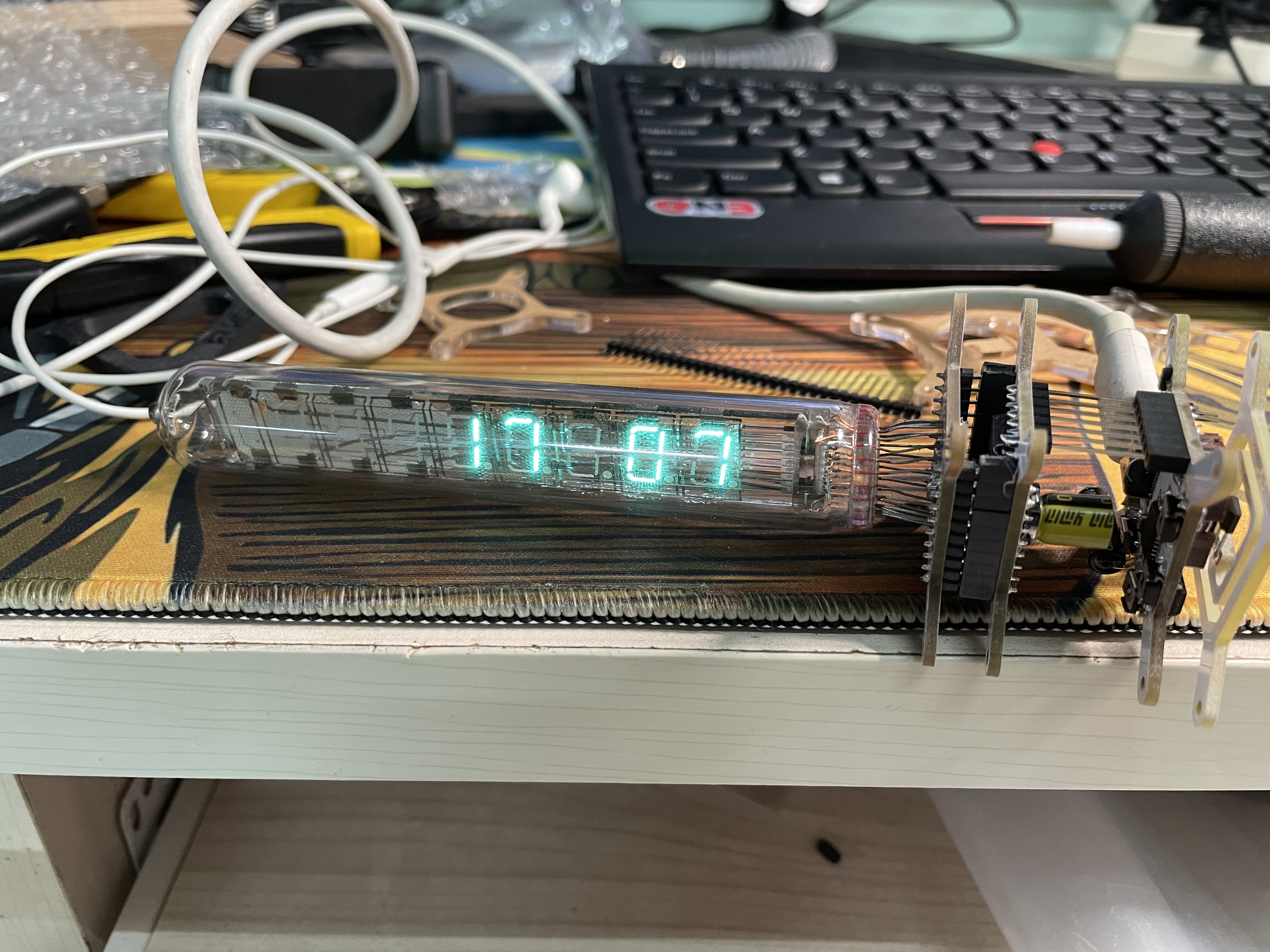
The VFD is displayed normally for the first time
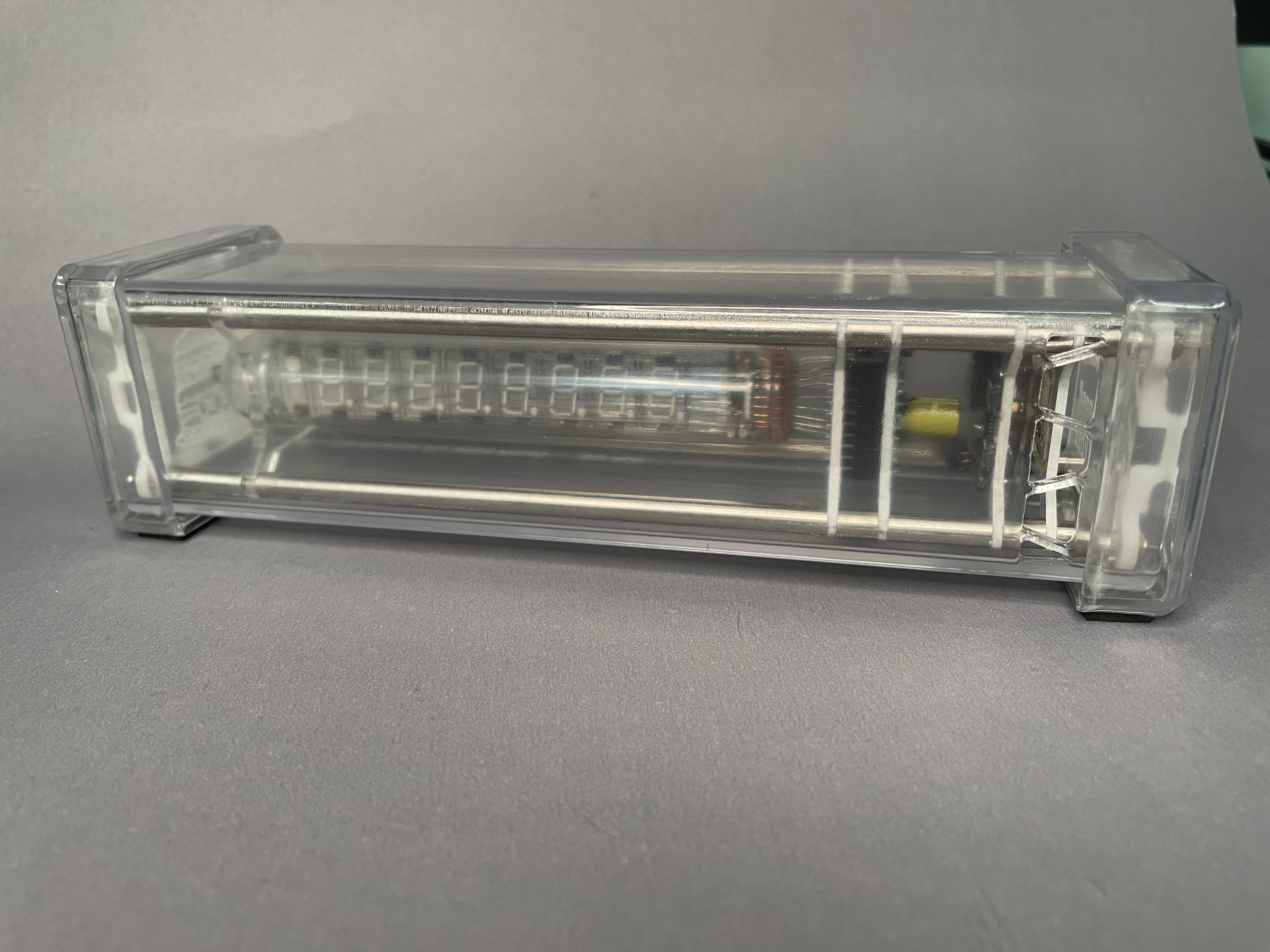
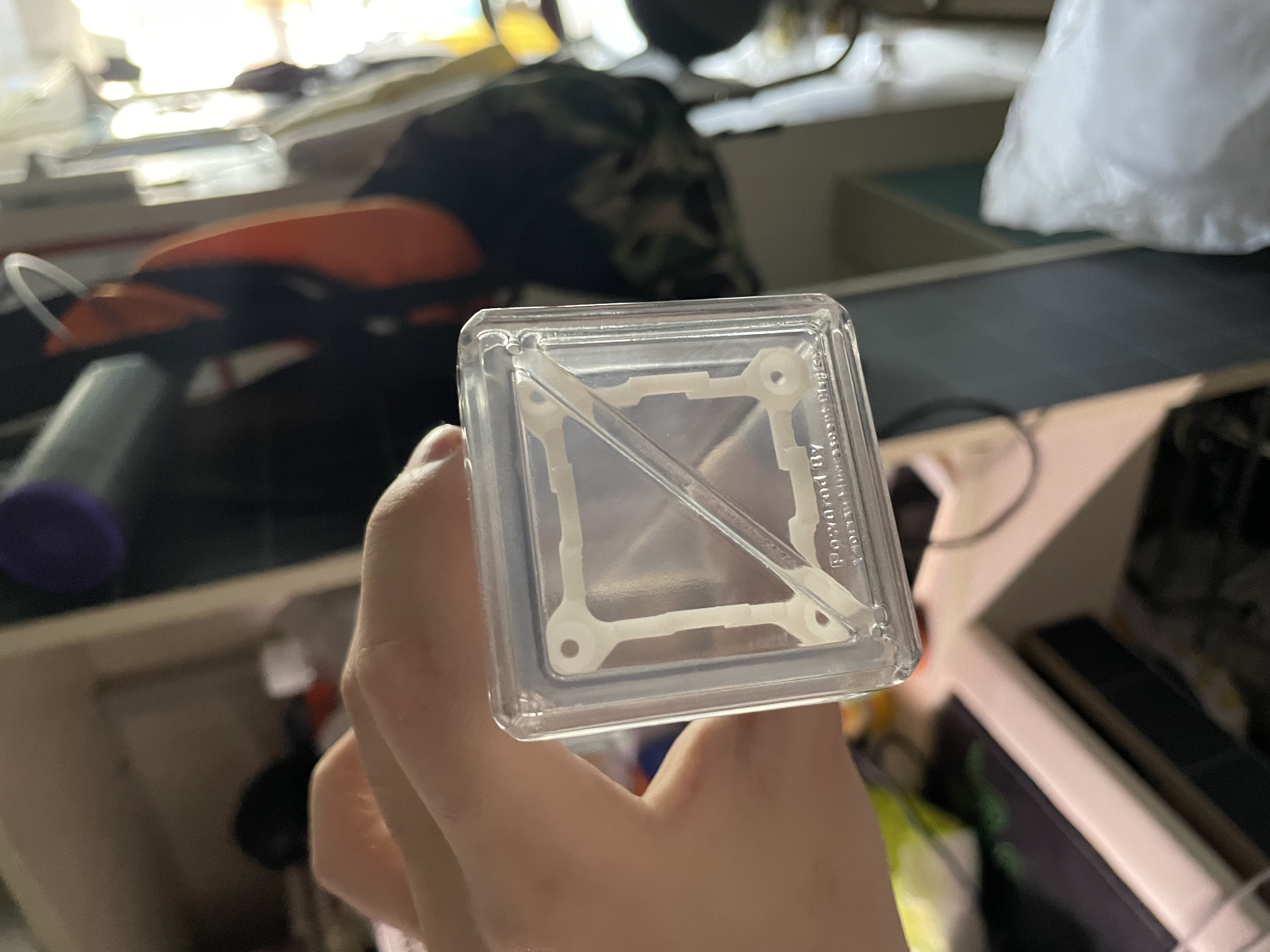
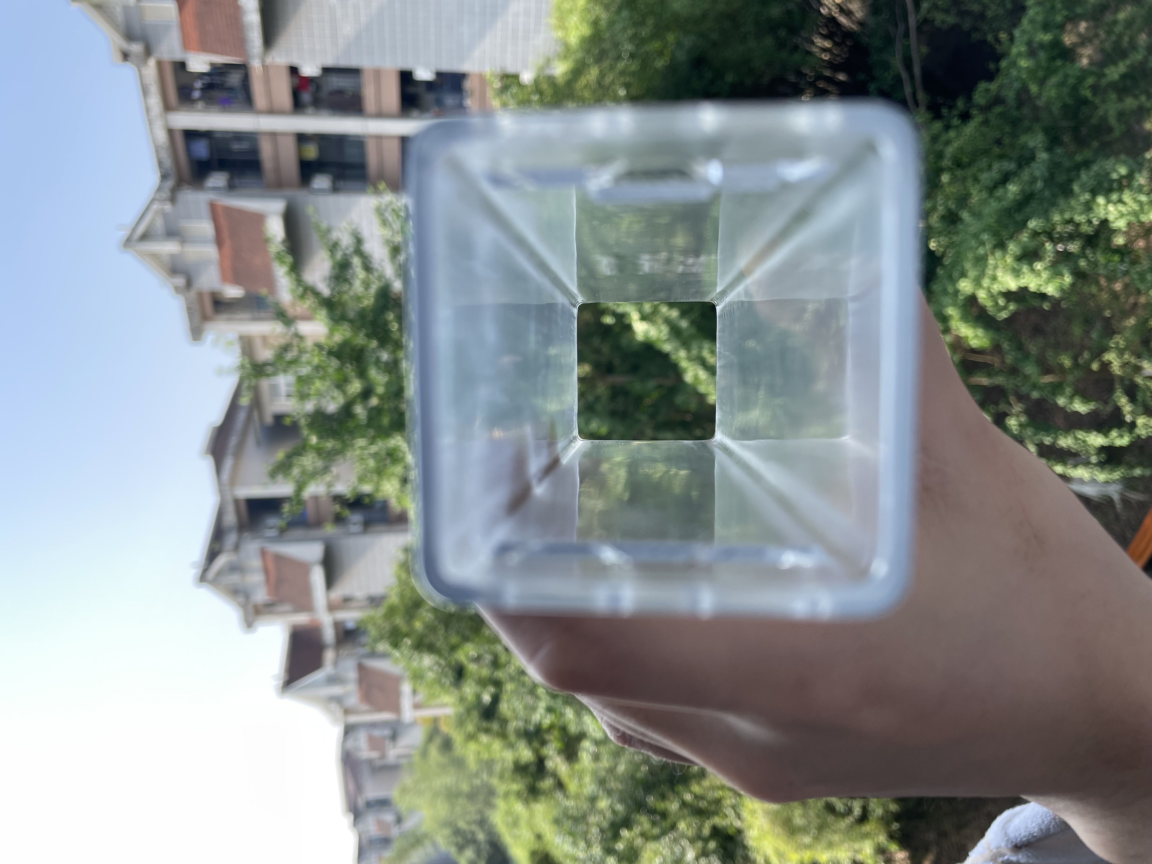
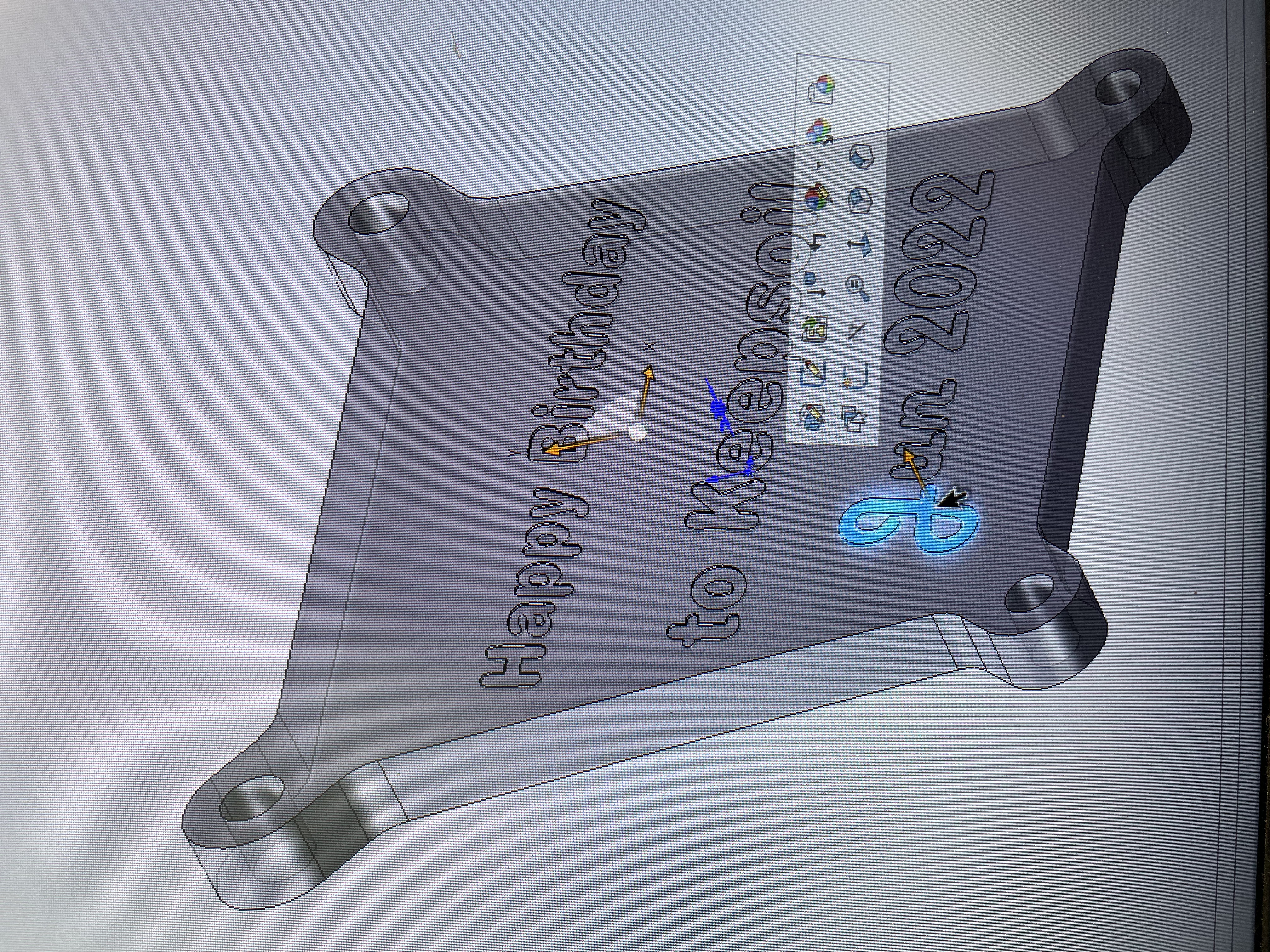
I used SOLIDWORKS to simply design a delicate, transparent 3D printed enclosure to protect a fragile circuit board
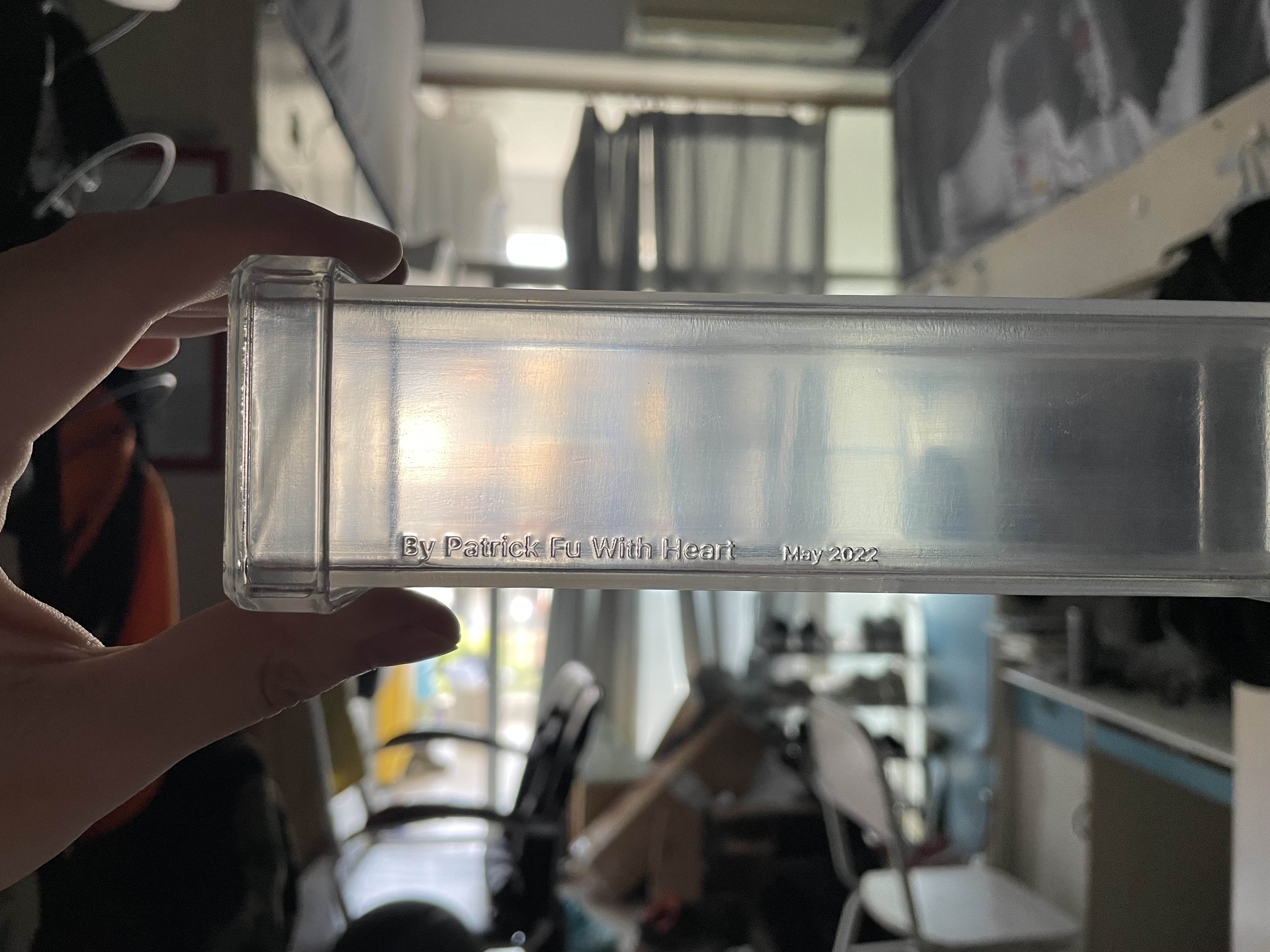
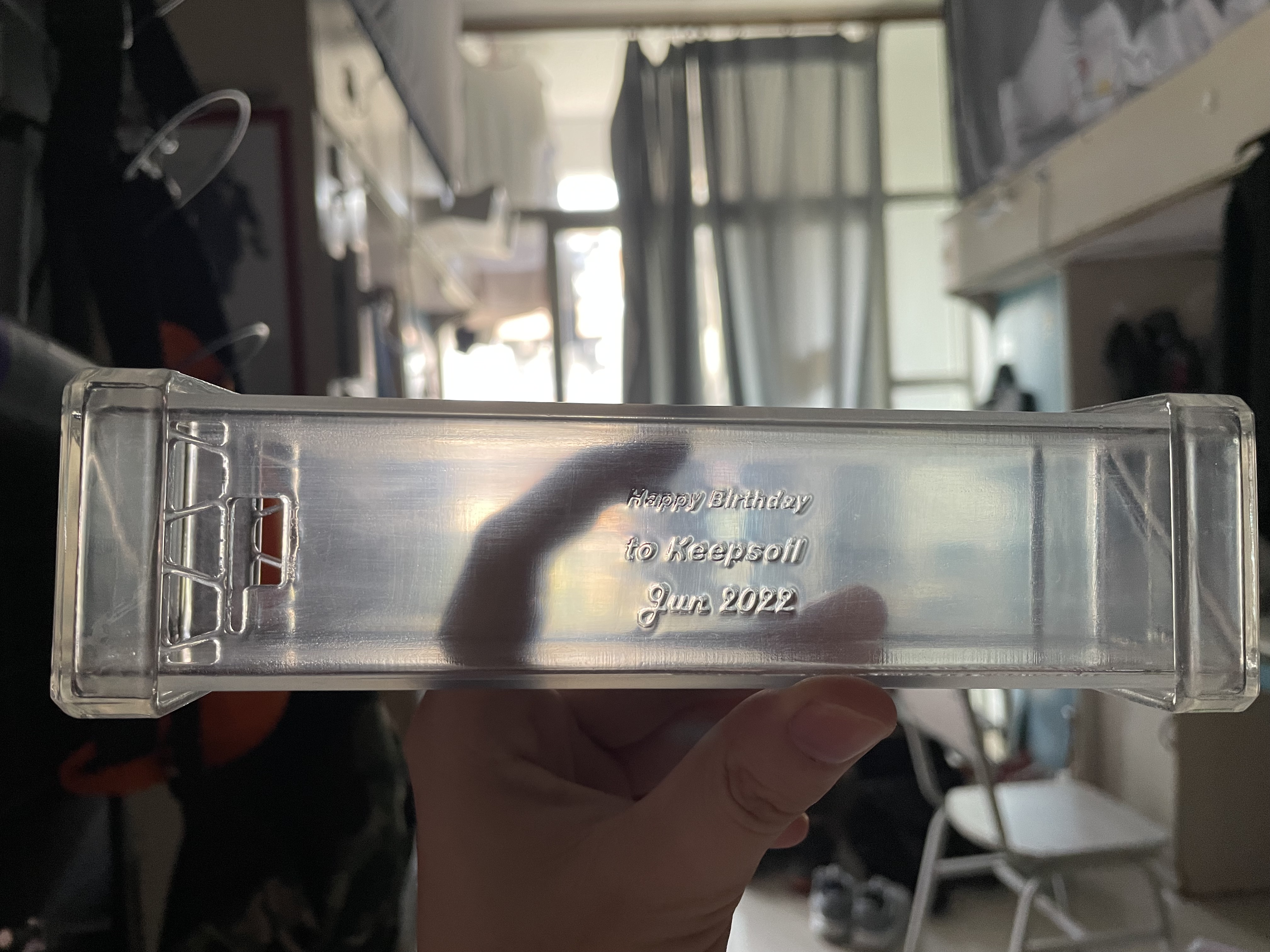
The reinforcement plates on both sides are made of acrylic and laser engraved with inscriptions
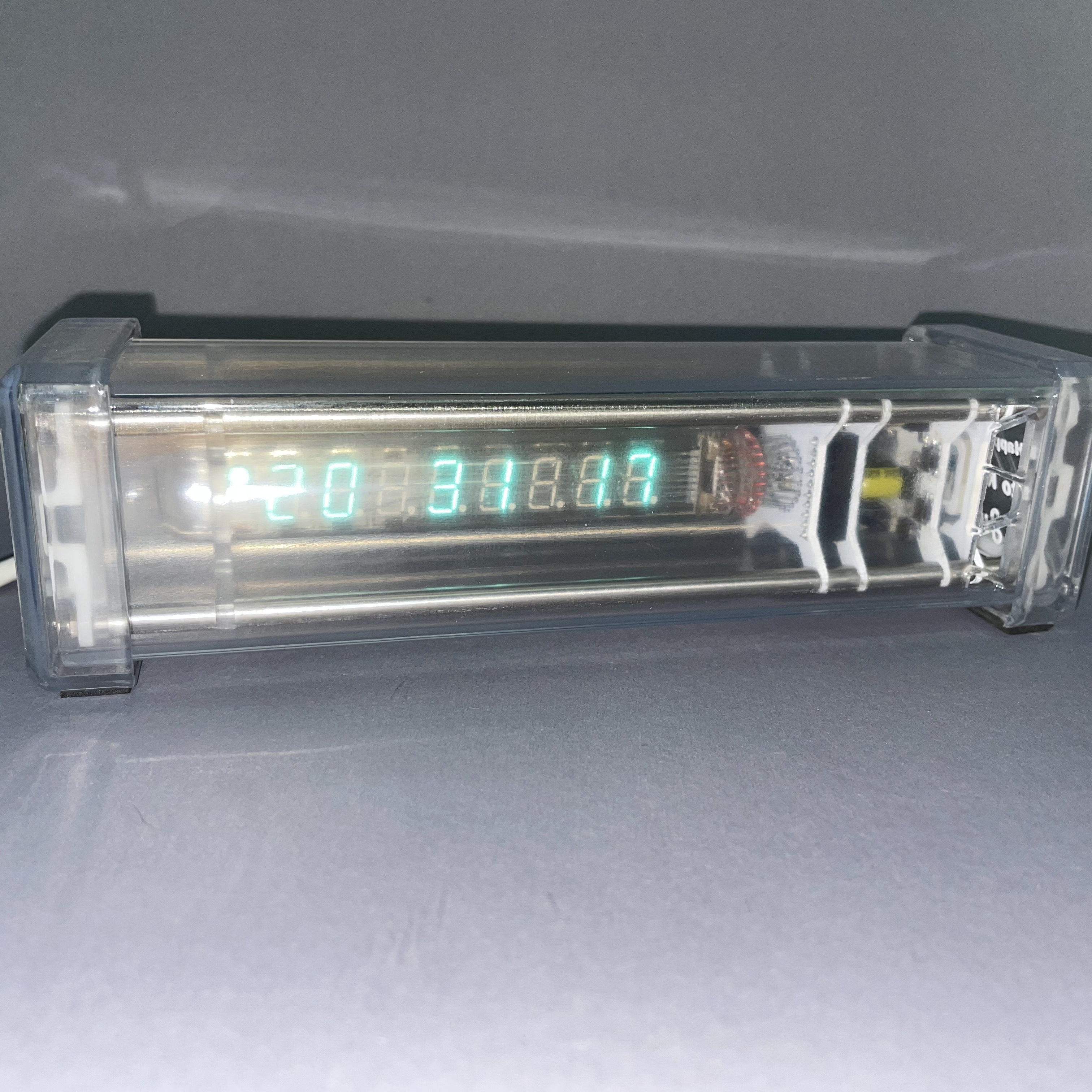
Artwork Display