Robot Design|MX_2 Engineer
A comprehensive introduction to MX_2 Engineer from the perspectives of design background, design metrics, mechanical design, hardware design, and software design

A comprehensive introduction to MX_2 Engineer from the perspectives of design background, design metrics, mechanical design, hardware design, and software design
Introduction to Robot Design Background
The core task of the engineer robot is to obtain gold ore from the large resource island in the center of the field and silver ore from the small resource island, and complete the exchange at the exchange station to obtain economic support for the whole team. This season, the method of exchanging ore for projects has changed a lot. The exchange station has been changed to a robot arm, and the exchange amount is also divided into levels.
According to the exchange rules of the new season, the economic gap brought by gold ore and silver ore has been reduced, and the economic gap caused by the difficulty of exchange has increased, and the accumulated economy is linked to the difficulty of exchange, so that each level can only exchange for two One gold ore plus five silver ores is equivalent to weakening the exchange speed requirements, and also greatly limiting the economic expansion advantage. The number of gold coins means the number of projectiles, and the number of drone calls includes the newly added this year to reduce the resurrection time of dead robots, which greatly affects the direction of the game situation. At the same time, when the ore is exchanged, the chassis is powered off, which increases the flexibility and freedom requirements of the exchange agency.
Therefore, this season’s engineering robot will focus on improving the degree of freedom at the end of the robot arm, reducing the need for exchange speed.
Robot Design Metrics
Engineer Robot’s function
Chassis function design
- There will be no rollover in all terrains
- Control the height of the center of gravity
- Maximum track width
- Strong mobility
- Four-wheel drive independent drive and suspension
Ores exchange module design
- The “three-phase gantry” is responsible for the movement of the end grabbing mechanism in the x, y, and z directions of the three axes
- The x and z axes are driven by motors and synchronous pulleys, and the x axis uses a rack and pinion double translation mechanism
- The y-axis is the double translation mechanism of the rack and pinion directly driven by the motor
- The three-axis robotic arm is responsible for the rotation of the roll, yaw, and pitch axes of the end grabbing mechanism
- 3508 motor direct drive
- The mechanism for grabbing ore at the end absorbs ore by ducted motor and suction cup structure
- The system is stable
- No obvious shaking of the robotic arm
- Reduce the probability of synchronous belt slipping
Other functions
- Easy to maintain
- Small module damage can be repaired within 2 minutes
- Large module damage can be repaired within 3 minutes
- Use m4 screws and nuts as far as possible to facilitate replacement and maintenance
- High stability, not easy to damage
- The overall shape is elegent and generous
Examples of functional quantification
-
The withdrawal and exchange system is stable
- The number of times of synchronous belt sliding teeth in the up and down process of the lifting mechanism is 0 for 100 consecutive times.
- The number of sliding teeth of the synchronous belt in the stretching process of the forward mechanism is 0 for 300 consecutive times.
- When the suction cup holds the ore horizontally, give the ore a vertical impact force of 50N, and the ore will not fall.
-
Extended requirements for mining and exchange
- The maximum lifting height (mm) is greater than 600 and less than 750, (the three-axis mechanical arm can provide a 410mm extension distance)
- The minimum reach (mm) meets [-450,100], and the maximum does not exceed [-500,150], (three-axis mechanical arm arm can Provide 410mm extension distance)
- The minimum traverse distance (mm) meets [-400,400], and the maximum does not exceed [-550,550]
Introduction to Mechanical Structure Design
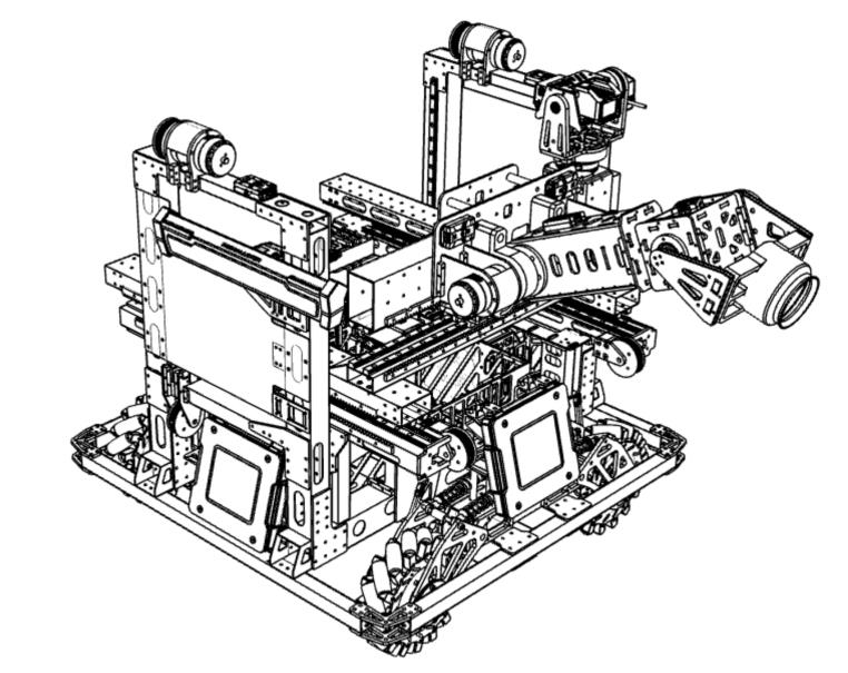
Engineer robot blueprint

Real photo of the Engineer robot
Chassis Layout
The chassis layout of engineering robots adopts the conventional four-mecanum wheel layout. Compared with the four-omnidirectional wheel layout, the robot in this layout has a faster linear motion speed under the same power and load. If the omnidirectional wheels move in a 45° direction, then Under heavy load, the damage to the two motors is slightly greater, and the other two wheels also provide a certain amount of friction, especially on undulating roads, which will seriously affect the movement; compared with the steering wheel, the wheelbase in the same frame is larger, and it is less prone to overturning , and the chassis load is reduced, and the speed of acceleration and operation is faster, which is more conducive to the tactical significance of engineering robots.
Design of Robot Grabbing Mechanism and Chassis Connection
This engineer robot innovatively uses the grabbing mechanism and the maximum speed direction of the chassis is 90°. This layout makes the wheelbase further utilized, because the left and right wheelbases of the mecanum wheels are the largest among the above three types when they are orthogonal. . Although a larger wheelbase can be obtained with an inclination of 45°, it is more difficult to design the mechanism layout for grabbing ore. The wheat wheel set we choose has a radius of 65mm and a width of 65mm. In the design of the robot in this project, the tilting angle of the y-axis reaches 58° and the tilting angle of the x-axis reaches 50° in the no-load contraction state, which fully guarantees its up and down 30°. It will not roll over when going up a slope. At the same time, consider that the robotic arm stretches forward by 410mm (the y-axis of its center of gravity changes by about 220mm), and the “three-way gantry” stretches forward by 200mm. Coupled with the fact that the end absorbs an ore, the overall center of gravity of the engineering robot will eventually shift 150mm to one side, which will cause the engineering robot to overturn at about 30°, but considering that this extreme situation is only encountered when grabbing/exchanging ore , the ground is flat at this time, so it is acceptable.
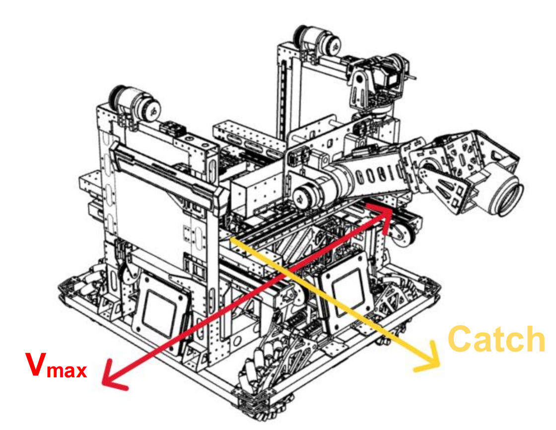
Chassis Vector Schematic
Design of Robot Arm
The combined layout of “three-way gantry” and three-axis mechanical arm. Compared with the six-axis robot arm, the advantage of this layout is that it is relatively easy to calculate the space on the control and reduce the pressure on the motion control; in terms of cost, the existing RoboMaster M3508 brushless geared motor can be used, and there is no need to purchase additional high-performance joint motors, reducing the cost. cost consumption. The three-axis robotic arm has already met the needs of picking up ground ore, and there is no need to install an additional ground picking mechanism, which achieves the purpose of reducing weight and operation difficulty. However, this solution also has obvious deficiencies, because although the end of the mechanical arm integrates two rotational degrees of freedom, there is still obvious coupling between the roll axis roll of the robot and the z axis lift. Since the rule has a maximum extension size of 1200mm, so The highest point of the lifting mechanism does not exceed 780mm. As a result, the third-level difficulty of the exchange station in the range of 780-900mm may have a situation where the roll angle cannot be reached and cannot be exchanged. It needs to be refreshed, which greatly lengthens the time for ore exchange.
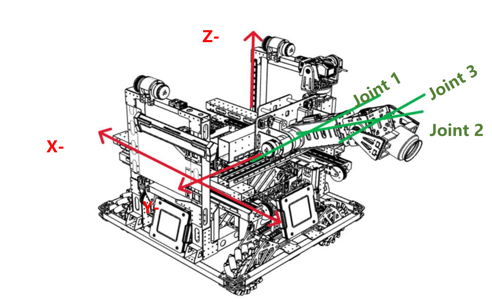
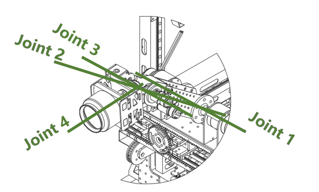
Robot arm joint design
Design of Ore Gripping Mechanism
The end effector used to obtain the ore props made of EVA uses a ducted brushless suction cup, which is a module modified by rewinding the existing vacuum cleaner fan on the market. The module has high full voltage and high efficiency, and can be powered by a single DJI TB47S battery (a total of two DJI smart batteries on the engineering robot are jointly powered) to meet the requirements of “the suction cup absorbs the ore horizontally, and gives the ore a vertical 50N The design requirements of the impact force, the ore will not fall”. Limited by the test equipment, and it is impossible to accurately read the specific suction force of the suction cup and the force required to forcibly remove the ore. Compared with the vacuum pump, the ducted brushless suction cup is lighter in weight, smaller in size and lower in power consumption while meeting the requirements of the competition, which is more conducive to the endurance performance of engineering robots, and reduces weight to increase mobility. At the same time, in view of the fact that the influence of circuit wiring on mechanical movement is far less than that of the air circuit layout, the direct end of the ducted brushless suction cup motor is placed directly connected to the 3D printed suction cup, which avoids the suction loss caused by the air circuit pipeline and reduces It eliminates the movement restriction caused by the air path arrangement and increases the flexibility of the end; the disadvantage is that the weight of the end is relatively increased, but the result of our evaluation of this design is that the weight is acceptable. The 3D printed integrated suction cup has better sealing performance, and a reasonable design can make better use of space.
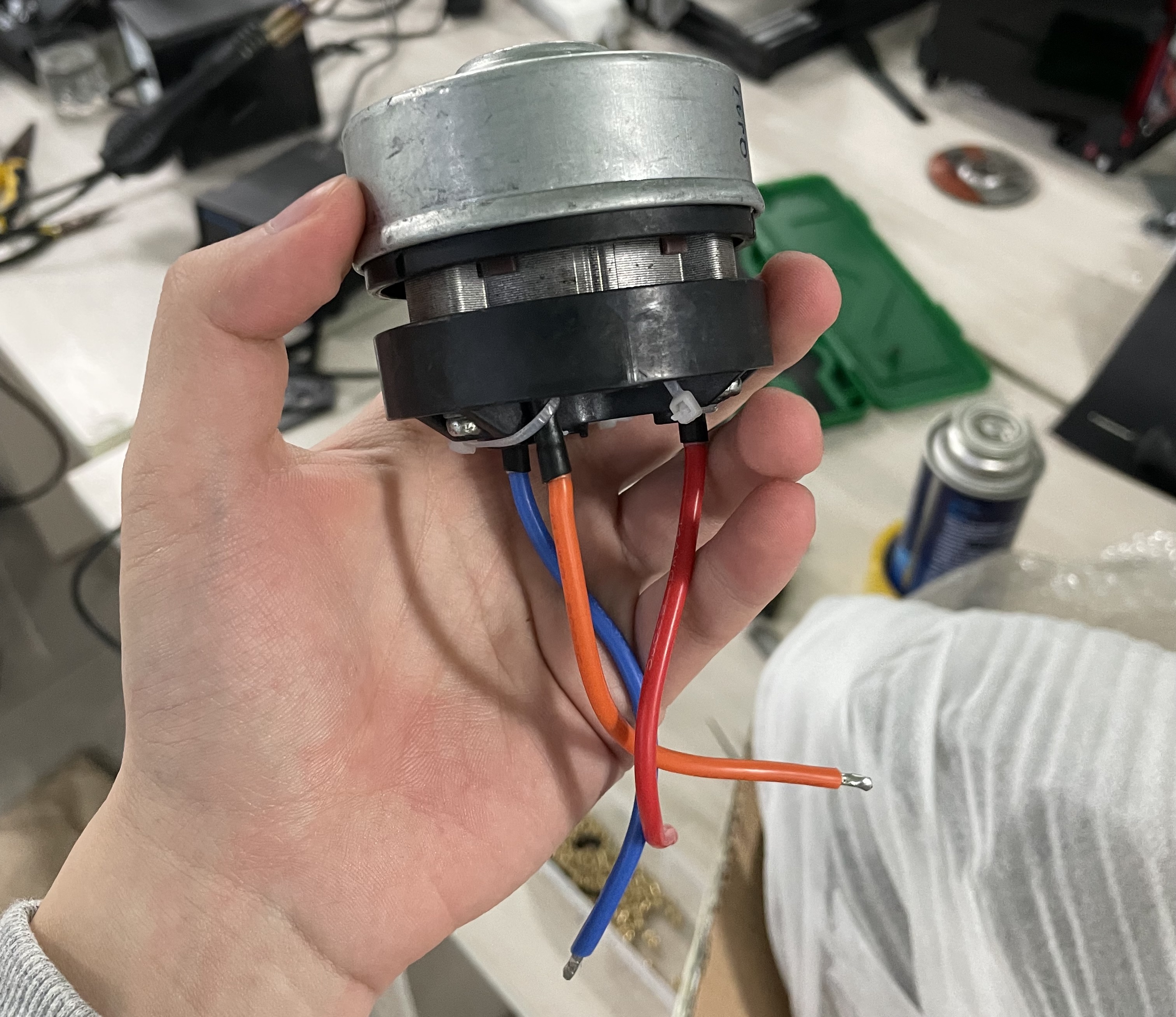
Brushless suction cup motor
Introduction to Hardware Design
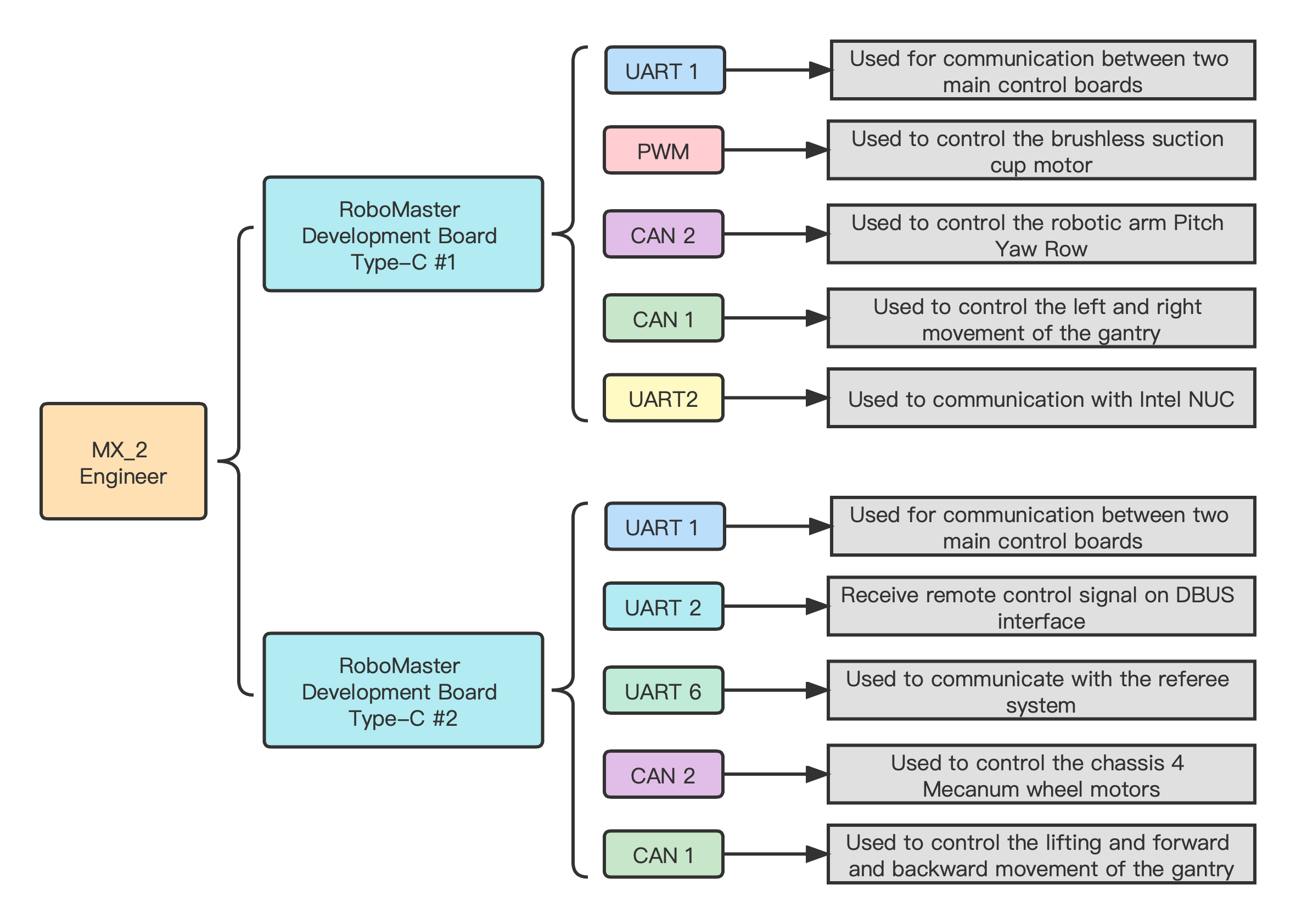
Due to the complexity of its own structure, the engineer robot uses as many as 12 brushless geared motors, uses two smart batteries, and is also equipped with Intel NUC, Brushless Suction Cup Motor, referee system and other equipment. **It is important to have a detailed topology plan for its electronic equipments.**We have designed a very concise power supply and signal transmission topology to facilitate inspection and repair.
Block Diagram of Robot System
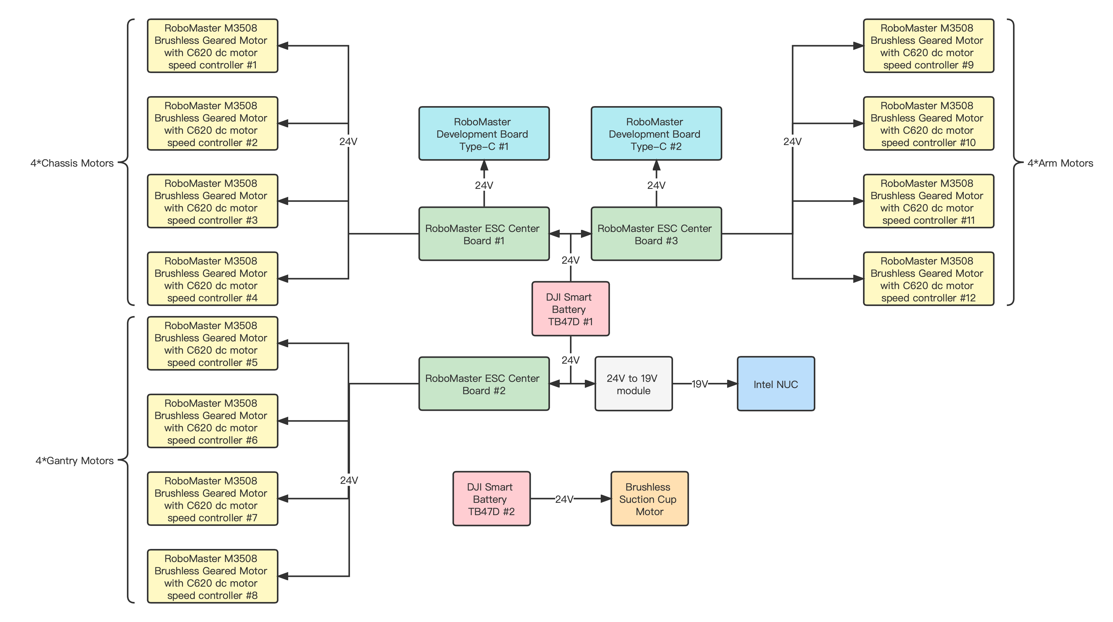
Block diagram of robot power supply system
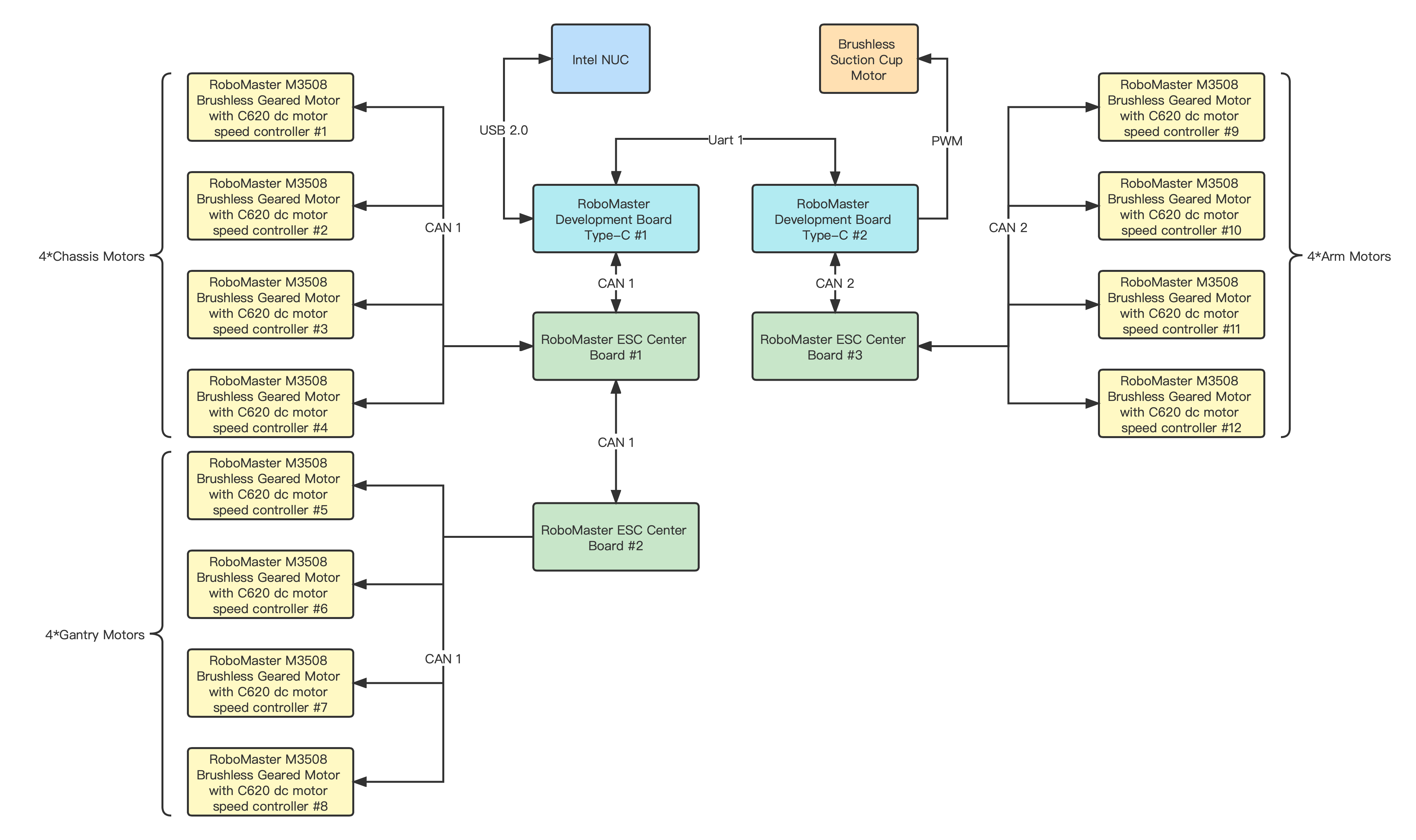
Block diagram of robot signal transmission system
Introduction to Software Design
The STM32 control code of team MechaX robots is highly modularized, and the code reuse degree is high. This greatly shortens the development time of robot motion control software.
All the robots in our team use a similar code framework, take MX_2 Engineer as an example to explain:
System Task Architecture
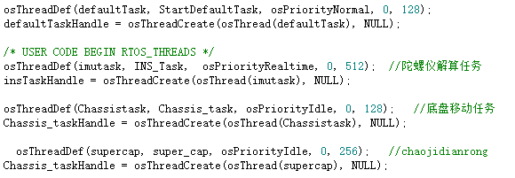
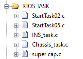
System Task Architecture
Key Functions
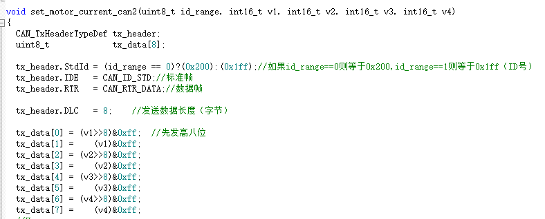
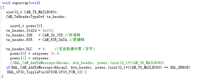
CAN Driver
Use CAN to pass gyroscope data between the upper and lower C-boards:
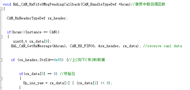
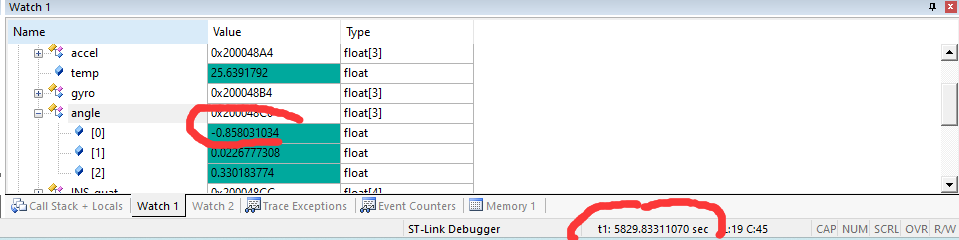
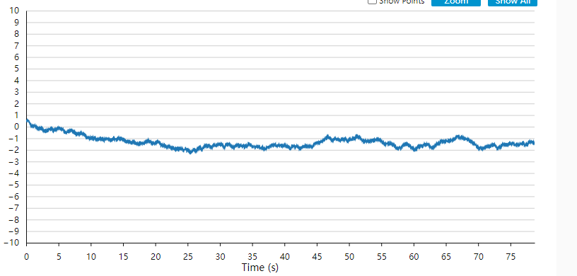
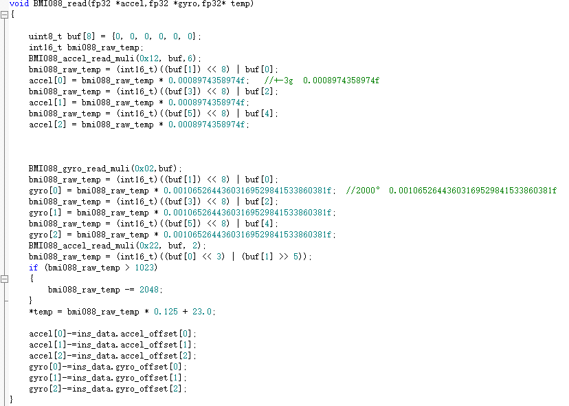
Gyro
Successfully obtained gyroscope data, which provided a basis for subsequent tasks such as attitude calculation and spin
Read gyroscope data:
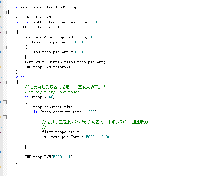
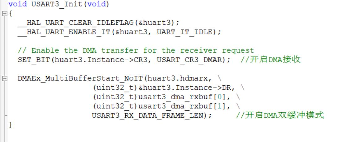
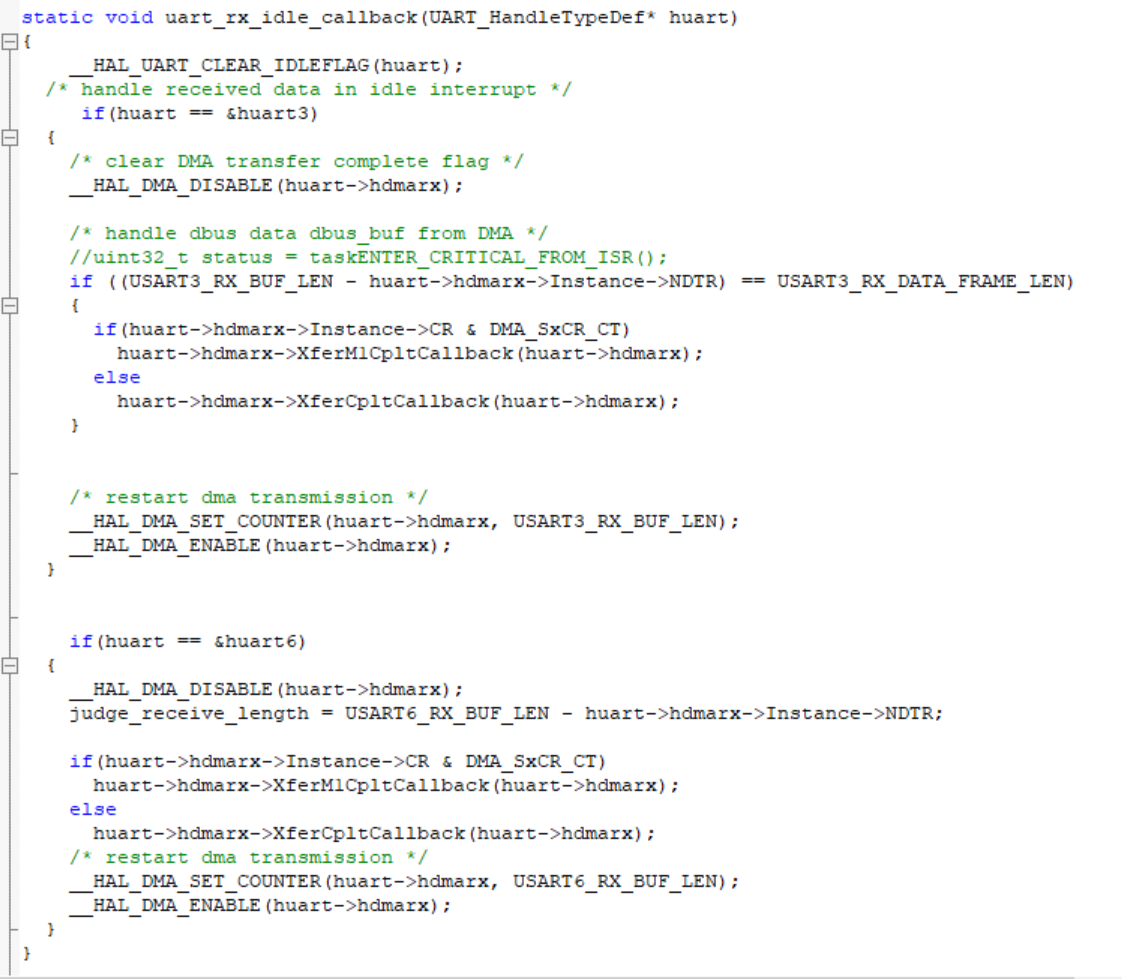
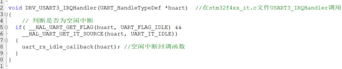
Serial Port Communication
Use RoboMaster Development Board Type-C USART3 to communicate with the remote control, and use USART6 to communicate with the referee system. In order to increase the communication rate and ensure the stability of the communication, the above two serial communication uses the serial idle interrupt plus DMA dual buffered mode. Various initialization configurations of serial communication are written in drv_usart.c.
Part of the code is as follows:
Summarize
Our team MechaX engineer robot is a complete project on robotics, including machinery, hardware, and software. The robot design process also exposed many of our design problems, and we improved them to improve the design level.
Although the robot still has problems such as vacancies in the mechanical arm and imperfect batch processing action groups, it has realized basic functions and can complete The task of absorbing ore props. We will continue to improve the robot’s intelligent system to realize the robot’s automatic completion of tasks.
