Course Project|Manufacturing

Introduction to Manufacturing course projects. Our team designed a gear system suitable for the RoboMaster competition through material selection, processing technology selection, structural design simulation, strength verification and sustainability analysis.
Project Introduction
Using the theoretical and practical knowledge of product manufacturing learned this semester, our team designed a gimbal yaw axis gear applied to the hero robot in the Robomaster competition. Its characteristics are:
-
High precision: realize that the robot gimbal can accurately aim at the target
-
High reliability: the gimbal can run stably for a long time, is not easy to be damaged, and has a long service life
-
High torque output: enables the robot gimbal to quickly adjust the direction during the game
-
Low weight: Reducing the weight of the robot helps to improve the flexibility of the robot’s movement
Our design features are:
In terms of technology, we chose the method of metal additive manufacturing, using 316L stainless steel for metal 3D printing to manufacture stainless steel gears. The rest of the main parts are made of carbon fiber CNC engraving and CNC aluminum alloy. At the same time, we also plan to spray Teflon on the contact surface of gears, which can play a role in lubrication.
Project Background
This project focuses on hero robots in RoboMaster competitions. In the RoboMaster game, the design of hero robots has gradually converged after several years of development, forming a complete design framework. This benefits from the excellent open source mechanism of the competition forum and the active exchange between the participating players.
Through the open source mechanism of the competition forum, the participating members can learn from the excellent design of other participating teams in the competition and improve it. At the same time, due to open source design, some excellent design schemes have also been quickly concerned and applied by everyone, becoming a general design standard. The establishment of such design standards makes the design of hero robots gradually converge, and the design plans between different teams gradually approach, forming a complete design framework. This design framework plays an important role in the design of hero robots, so that the team can design robots more systematically, so that they are more practical, competitive and reliable.
In this design framework, the chassis of the hero robot generally adopts the McNamwheel scheme, which can achieve good direction control and movement ability and improve the stability of the robot. The upper structure of the hero robot adopts a fan-shaped structure or circular structure, which fixes the cloud table and gun tube relatively and improves the stability of the center of gravity of the robot. At the same time, the cloud platform and barrel of the hero robot are arranged at a good angle, which can improve the shooting angle range of the robot.
In addition, according to the rules and experience of the game, the design of the hero robot needs to consider the cartridge, the fetching device, the chassis protection and other additional functions. For example, in the design of the cartridge, some teams will use the design of the chassis cartridge, so that the robot can maintain better stability and mobility in the game; and in the design of the retrieving device, there are also many creative design options, such as robotic arms, “nine-tooth rake” retrieving the cartridge and other ways.
Therefore, the design framework of hero robot not only includes the design of mechanical structure and electronic control parts, but also involves many aspects such as tactical strategy, competition rules, and experience summary. The team needs to be based on this, combined with their own actual situation and competition experience, flexible design and optimization, in order to improve the competitive ability and practicability of robots.
Hero robots first appeared in the RoboMaster 2016 season and were the first type of robotic weapon to appear in the game, including hero robots, infantry robots, aerial robots, and base robots. During this period, the hero robot had a blood volume of 5000 points, fired a 42 mm projectile with a damage volume of 500 points, and needed to obtain the projectile on the resource island before it could be launched, causing damage. Therefore, hero robots in this period need to design specialized up-step crossing obstacle mechanisms for better access to projectiles. At the same time, there are 20 golf projectiles stored above the stop column of the competition site, and the aerial robot can design a grasping mechanism to obtain the projectiles at this site and supply the projectiles to its own hero robot. The design makes the hero robot have combat effectiveness and competitive ability in the competition.
In this period, the design of hero robots also has different typical designs from later ones. The cloud deck of the hero robot is generally arranged in the chassis position, while the projectile and projectile taking device are installed close to the top of the robot. This design makes the center of gravity of the hero robot more stable, can be more flexible in competition, better move and avoid attacks, and has a better hit rate and launch effect.
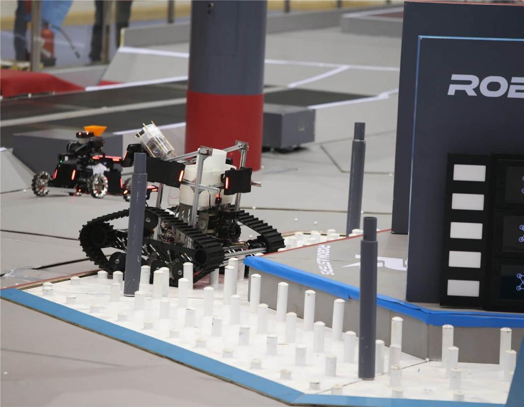
Fig.1 RoboMaster 2016 Hero Robot Login Resource Island
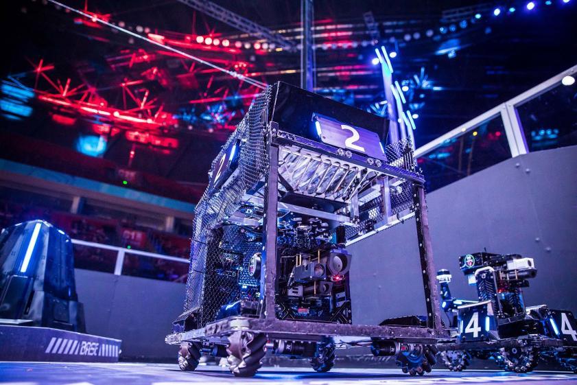
Fig.2 RoboMaster 2018 Hero Robot
In the RoboMaster competition in 2018, a significant technology, computer vision technology, emerged to locate enemy armor plates and achieve automatic aiming. In order to prevent the effect of automatic aiming from being weakened by the opponent, the team also used the twist waist mode to allow the chassis to twist reciprocally and reduce the enemy’s hit rate. However, in such a competitive environment, the team of China University of Mining and Technology adopted the small gyro technology for the first time, which allows the cloud table to rotate 360 degrees relative to the chassis by installing an electric sliding ring at the connection between the yaw axis of the infantry robot cloud table and the McNam chassis. During the game, they let the head of the robot point unchanged, while the chassis rotates continuously while moving back and forth. Using the superposition of x, y and spin speeds, the accuracy of the computer visual prediction model is significantly reduced, thus reducing the effect of automatic aiming. Through the application of small gyro technology, China University of Mining and Technology successfully prevented the automatic aiming of opponents, improved their own competitive strength, and also brought new ideas for the development of RoboMaster competition technology. This technology can be said to be a technical turning point of the RoboMaster competition, and its application in this robot competition has set off a new trend and led to a new round of technical revolution in this competition.
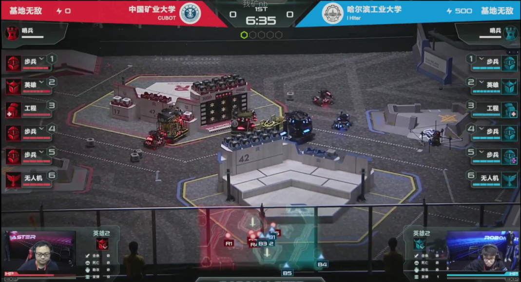
Fig.3 Red square 5 infantry aligned with Blue square 1 infantry using small gyro movement on the field achieved significant advantages
Since the RoboMaster 2019 season, hero robots have been explicitly banned from acquiring projectile boxes, and instead engineering robots take projectiles and hand over to hero robots. At the same time, the chassis power of the hero robot decreased from 120 w to 80 w, and the installation position of the large armor changed from the top to the bottom of the robot. The above changes have prompted the transformation of hero robots from bulky to flexible.
The typical hero robot in 2019 (Figure 4) was very eye-catching in the RoboMaster game. The robot adopts a new design scheme that stores large projectiles on top of the robot and connects them to the cloud platform launch mechanism using hoses. Compared with the previous hero robot, the robot removes the traditional projectile taking mechanism, thus greatly reducing the weight of the robot. This design not only improves the mobility and flexibility of robots, but also further reduces the burden of robots carrying ammunition, so that robots are lighter and more efficient in combat. At the same time, this design scheme also helps to improve the stability and accuracy of the robot. Since the projectile is stored at the top of the robot, the bottom of the robot can be better close to the ground, thus enhancing the stability of the robot; and the separation of the position of the launch mechanism from the stored projectile also helps to reduce the vibration and interference during launch and improve the launch accuracy of the robot.
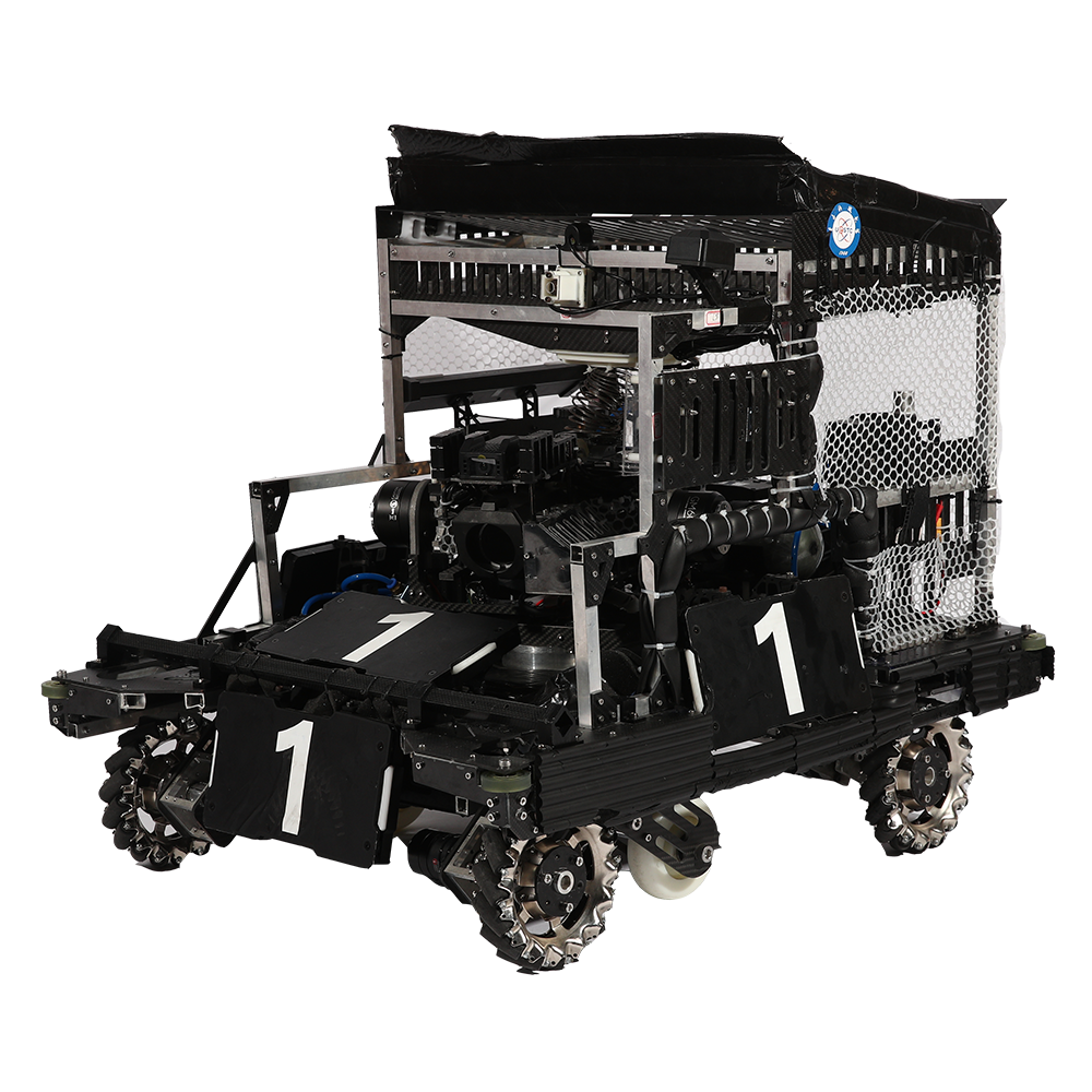
Fig. 4 RoboMaster 2019 University of Electronic Science and Technology Hero Robot
The robot BADBOY designed by Shanghai Jiao Tong University in 2019 is an innovative Hero robot. Unlike traditional hero robots, BADBOY uses the design of chassis cartridge, which is placed in the robot chassis and transports the ammunition to the friction wheel launch mechanism through the high-torque dial and rigid transmission link, so as to achieve ammunition launch.
This design has many advantages over traditional hero robots. First, due to the design of the chassis cartridge, the whole robot becomes extremely lightweight, has higher mobility and better maneuvering ability, and can quickly move and avoid enemy attacks during the game. Secondly, this design scheme also improves the stability of the robot and reduces the vibration during the launch, thus making the launch more accurate and stable. In addition, this design scheme also increases the loading capacity of robots, improves the combat persistence of robots, and makes robots more competitive in competition.
Besides the innovative design of the chassis cartridge, the BADBOY robot has other innovative features. For example, it installs a hollow electric sliding ring, so that the wire can be unrestricted when the robot rotates; it can also realize gyro motion, maintain a more stable state when moving, and improve the mobility and stability of the robot.
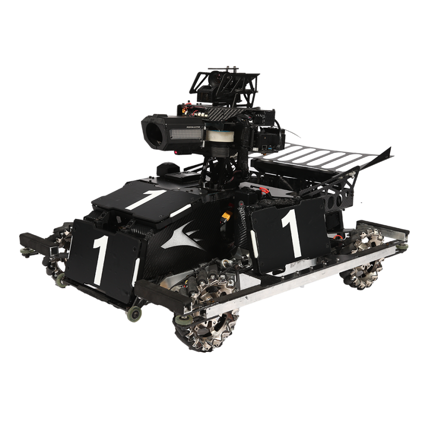
Fig. 5 RoboMaster 2019 Shanghai Jiao Tong University Hero Robot BADBOY
Material Selection
Gear Material Selection
The selection of gear material is 316L stainless steel, and the following points are mainly considered in terms of its performance:
-
Corrosion resistance: 316L stainless steel has excellent corrosion resistance and is especially suitable for use in harsh environments. This is important for gears, which are often subjected to lubricants, water, or other media that may cause corrosion.
-
Mechanical properties: 316L stainless steel has good mechanical properties, including strength and toughness. This is critical for the gear, as the gear needs to withstand high loads and repeated stresses while maintaining a stable shape.
-
Ability of metal 3D printing: 316L stainless steel is one of the materials suitable for metal 3D printing. Metal 3D printing technology enables complex shape gear manufacturing, including internal structure and customized tooth shape. This flexibility can optimize the performance of the gear and improve efficiency and durability.
-
Temperature resistance: 316L stainless steel has good high temperature resistance and is suitable for gear applications operating in high temperature environments.
In summary, 316L stainless steel is suitable for manufacturing gears, especially when corrosion resistance, mechanical strength, and complex shapes are required. The choice of 316L stainless steel allows fabrication of high precision and complex shapes while maintaining the mechanical properties and durability of the gear.
Material Selection of Transmission Parts
For the other drives, we chose 6061 aluminum alloy. The transmission parts other than the gear still have certain strength requirements, and it is necessary to ensure the efficiency of transmission. The following are some of the reasons for choosing 6061 aluminum alloy as the driver material:
-
Strength and lightweight: 6061 aluminum alloy has good strength and rigidity, can withstand a certain load and stress. The density of aluminum alloys is relatively low compared to other metals, so lightweight design of transmission parts can be achieved. This is important to reduce the weight of the entire system and improve energy efficiency.
-
Machinability: 6061 aluminum alloy easy to process and cut, suitable for CNC processing. This material can provide high surface quality and dimensional accuracy, ensuring the accuracy and reliability of the transmission.
-
Corrosion resistance: 6061 aluminum alloy has good corrosion resistance and will not have corrosion phenomenon. In particular, it has good corrosion resistance to general atmospheric environment and many industrial media. This helps ensure the durability and life of the drive piece.
-
Wide application: 6061 aluminum alloy is widely used in various fields and applications, including automotive industry, aerospace, mechanical manufacturing and electronic equipment. This means that this material is extensively validated and has a reliable record of performance.
In summary, it is reasonable to choose 6061 aluminum alloy as a transmission material, which combines the advantages of strength, lightweight, processability and corrosion resistance. CNC machining technology can precisely cut and process aluminum alloys to meet the precision requirements of transmission components and ensure their performance and reliability.
Material Selection for Structural Parts
For structural parts, we chose carbon fiberboard. Carbon fiberboard is a relatively lightweight, strong and rigid structural material, which has the advantages of high strength, good compression performance, lightweight and corrosion resistance:
-
Strength and lightweight: Carbon fiberboard has excellent strength and rigidity and is lighter than many metallic materials. Its specific strength (the ratio of strength to density) is very high, which makes carbon fiberboard ideal for lightweight design of structural parts. Despite its relative lightweight, it still has excellent performance in carrying and supporting.
-
Corrosion Resistance: Carbon fiber is not subject to corrosion, which makes carbon fiber board perform well in structural component applications with long-term exposure to harsh environmental conditions.
-
Good vibration and energy absorption performance: Carbon fiberboard has good damping ability to vibration, which can reduce the resonance and vibration noise of the structure. In addition, carbon fibers have an excellent energy absorption capacity to absorb energy during impact and collision, providing better structural protection and safety.
-
Accordingly, carbon fiberboard is well suited for use as structural parts, especially when lightweight, high strength and stiffness requirements are required. For example, carbon fiber structural components are often used in aerospace and automotive industries. And our design is also its appropriate application scenario.
For our design, the greatest advantage of choosing carbon fiberboard lies in its contribution to lightweight, and the adaptability of the design under different systems can be improved by realizing the lightweight of the design as a whole.
Key Component Design and Modeling
Gear Design and Modeling
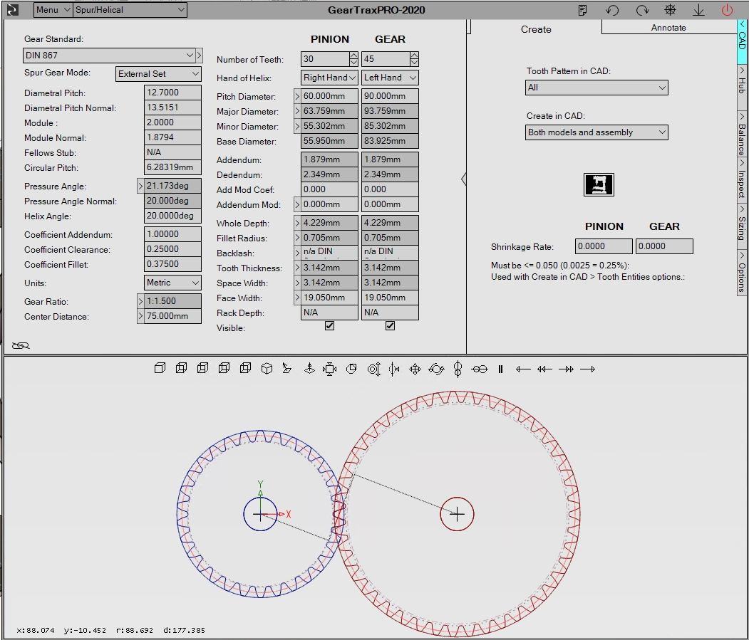
Fig. 6 GearTraxPRO Plug-in Interface and Helical Gear Parameters
The herringbone gears can be obtained by mirroring the common helical gears. When selecting the parameters for the bevel gear, several factors need to be considered:
-
Pressure angle: The pressure angle refers to the included angle between the force line on the gear tooth surface and the tangent line on the gear surface. In general, the greater the pressure angle, the strength of the gear, but the noise and wear will also increase, the force on the axis direction will also be greater. But because we use a herringbone gear, the forces on both axes counteract each other. The effect can be ignored, here we choose a pressure angle of 20 degrees, relatively large, can effectively improve the stability of force transmission.
-
Modulus: Modulus is the ratio of the width of the gear top to the number of teeth, that is, the width of each tooth. Modulus, gear strength, but size. A modulus of 2 is chosen here, the volume is small, and the overall proportion is coordinated
-
Number of Teeth: The number of teeth on a gear. The more the number of teeth, the load capacity of the gear, but the production difficulty and cost will also increase, because we use the form of additive manufacturing, the production difficulty and cost are basically not different. The number of teeth was selected as 30 and 45, respectively, to form a transmission ratio of 2:3.
-
Tooth shape standard: We select European standard DIN867. The linear units used in the DIN 867 gear standard are millimeters (mm) and the angle units are degrees (°). This standard specifies such parameters as the number of teeth, tooth shape, tooth distance and pressure angle of cylindrical gear. These parameters use millimeter as linear unit. For example, the units of tooth distance and tooth height are millimeter. The millimeter system ensures that the unit system is consistent with that in the design, which is very convenient for the design. In this design, the distance between the centers of two gears is 75 mm.
-
The chevron gear is obtained by mirroring the helical gear generated by the plug-in, and then the installation hole and weight reduction slot are modeled, forming the final design shown in figure 7.
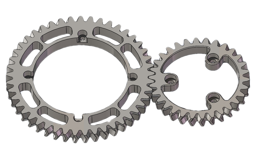
Fig. 7 Gear Display
Assembly Model
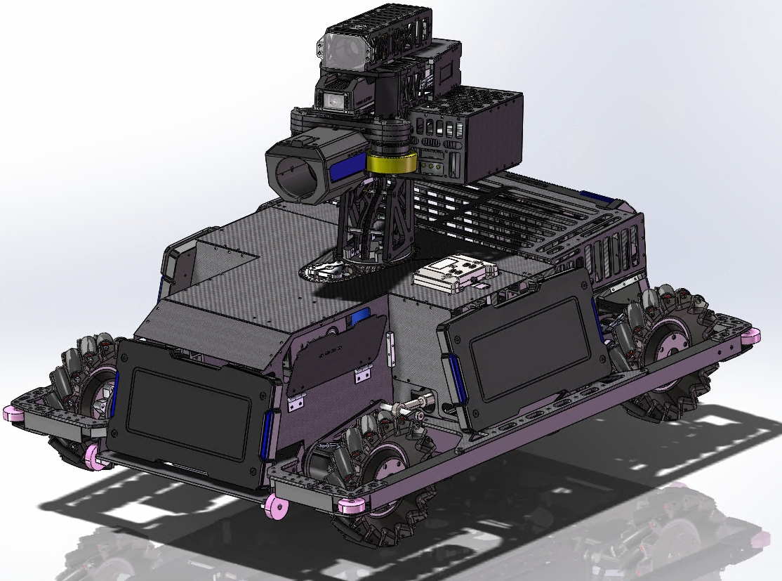
Fig. 8 Robot full model
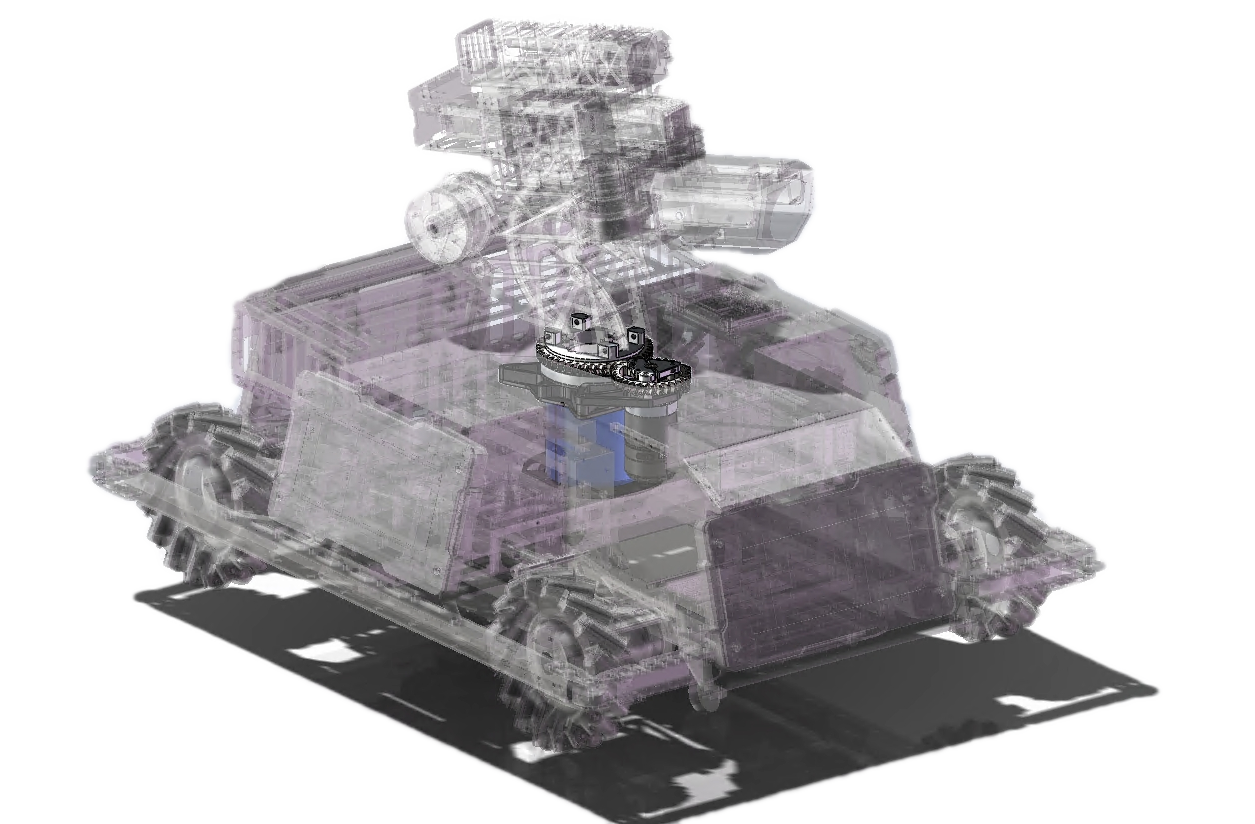
Fig. 9 Diagram of Yaw Axis Module Located on Robot Position
The complete model of the robot, the yaw axis located in the robot chassis and cloud table connection, has a crucial role.
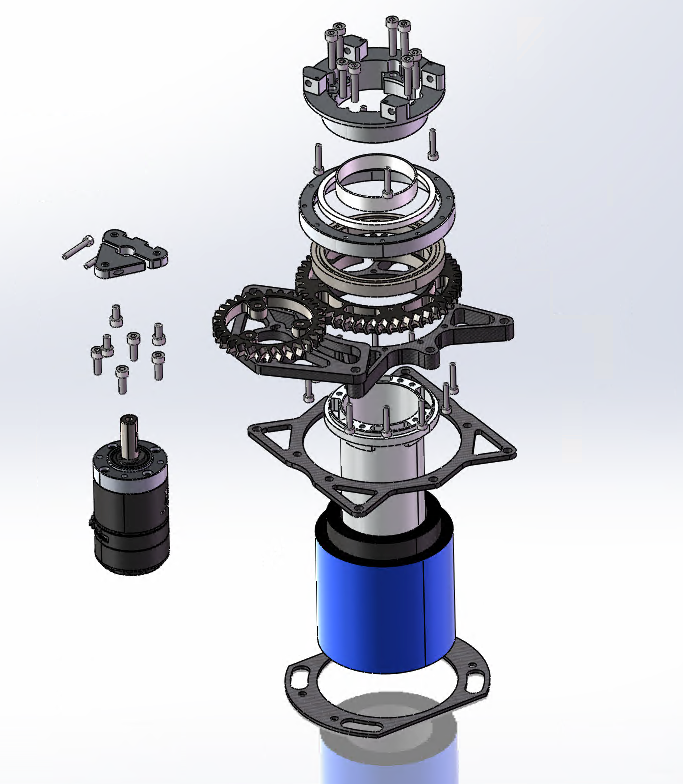
Explosion diagram of yaw axis module
The explosion display diagram of yaw shaft module is as follows, and the structure (from left to right, from top to bottom) includes gimbal motor, motor coupling, herringbone gear, gimbal connector, bearing pressure ring, yaw shaft bearing, yaw shaft structure beam, motor support plate, transmission tube and electric sliding ring.
Process Chain Selection
Gear Process Chain Selection
Process: Metal 3D Printing
The metal 3D printing process was chosen because it has the advantages of high precision, complexity, and customizability, which can create complex shapes and precise size requirements. In addition, manufacturing time and raw material waste are minimized by 3D printing, as the required materials can be added directly to the location of the building, reducing processing steps and scrap. Metal 3D printing technology can achieve very complex tooth shape and internal structure, achieve higher transmission efficiency, and avoid unnecessary material waste. In addition, metal 3D printing technology can fabricate components with accurate dimensions and specific material properties (such as 316L stainless steel containing 18% to 20% chromium, etc.), with controllability, excellent mechanical properties, and is not easy to deform, wear, corrosion and durable.
Post-Treatment Process: Milling and Spray Teflon Spray
When a gear is printed, the surface is rougher and needs to be abraded to improve surface roughness and surface quality. In addition, in order to reduce gear wear and prolong service life, Teflon spray needs to be sprayed on the tooth surface for lubrication. Spraying Teflon spray can reduce the loss and noise of gear, improve the operating efficiency and service life of gear.
In this design, a 3D printing mold specially used to spray Teflon spray is also designed. As shown in the figure, it is installed on the processing equipment rotating at a constant speed such as the lathe and sprayed in the hole, which can effectively prevent the spillage of toxic gas and ensure the uniform spraying.
Fig. 11 Teflon Spray Mold
Transmission Process Chain Selection
Process: CNC Process
CNC machining technology uses numerical control machine tools for cutting and machining, which can produce complex and high-precision components, with high machining efficiency, which can maintain environmental stability, while reducing material waste. The 6061 aluminum alloy was chosen because of its good strength and rigidity, which is very suitable for some moderately loaded transmission parts. In addition, this aluminum alloy is not easy to corrode and deform, and can effectively increase the service life of transmission parts.
Heat Treatment Process: No Heat Treatment Required 6061 aluminum alloy can be used directly after CNC processing without additional heat treatment process.
Post-Treatment Process: Polishing and Cleaning
Process Chain Selection for Structural Components
CNC engraving technology is a widely used processing technology nowadays, which can adapt to various complex shapes of parts and provide high-precision and quality manufacturing processes. Carbon fiberboard is a kind of excellent structural material, with excellent physical properties, strong rigidity, light weight, high tensile strength, and good corrosion resistance and high temperature resistance, which can be used to manufacture large, high-stress structural components.
For the selection of post-processing technology, special processing methods can be customized according to actual needs, such as surface spraying, adhesive film, etc., to improve the aesthetics and durability of structural components.
Model simulation and verification
First, we perform transient dynamics simulation of the meshing process of this herringbone gear to test whether there is a meshing problem during gear design, import it into Ansys and perform transient dynamics analysis on it, as shown in the following figure:
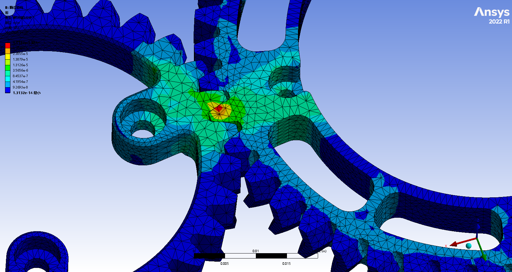
Fig. 12 Simulation results of transient dynamics of gear meshing
We found that the gear stress points were concentrated on the tangential meshing line of the two gears during meshing, which indicated that the gear meshing position was in the position expected by the design. The meshing line is the theoretical straight line between two gear surfaces, which determines the geometry and transmission ratio of gear meshing.
At the same time, we use Solidworks to simulate the weight loss and safety factor of key parts: motor support plate hollow out:
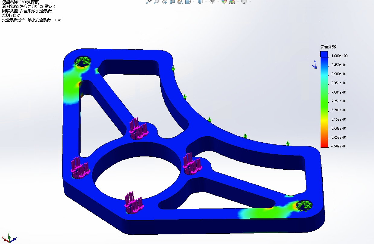
Fig. 13 Simulation results before mechanical optimization of parts
We found that there was a problem of stress concentration near the action two holes close to the part, and the overall safety factor was low, so such hollow plate was unsafe when used, so we used Ansys for topology optimization to clarify the modification direction and verify the safety factor of the structure:
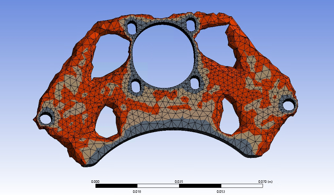
Ansys Topology Optimization Results
Therefore, we absorb the idea of topological optimization and obtain the following component diagram:
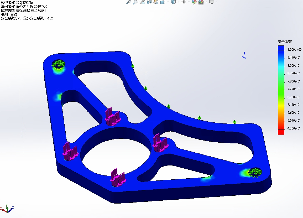
The modified parts according to the topology optimization idea
After understanding the trend of topology optimization and modifying the fillet parameters in the modeling, there is no obvious stress concentration in our simulation, and the safety factor has been significantly improved, which proves that it is relatively reasonable and safe to use it as a cloud platform component.
Afterwards, we use Solidworks Simulation to quickly verify the stiffness and safety factor of the beam of Yaw shaft structure, and obtain the image. The overall minimum safety factor is 2.4, and the maximum deformation is only 0.03 mm under the conventional load, which is obviously acceptable. Therefore, the design of this part meets the requirements
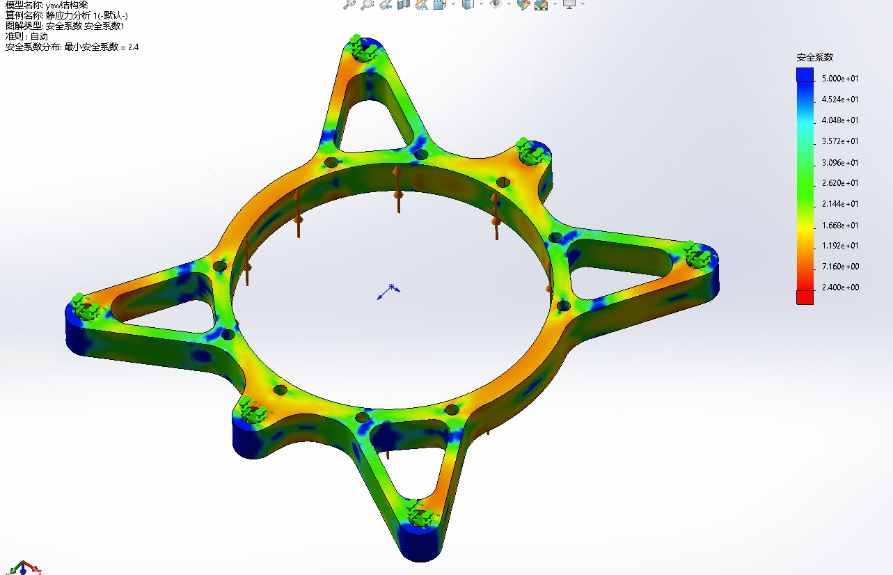
Safety factor simulation of Yaw axle beam
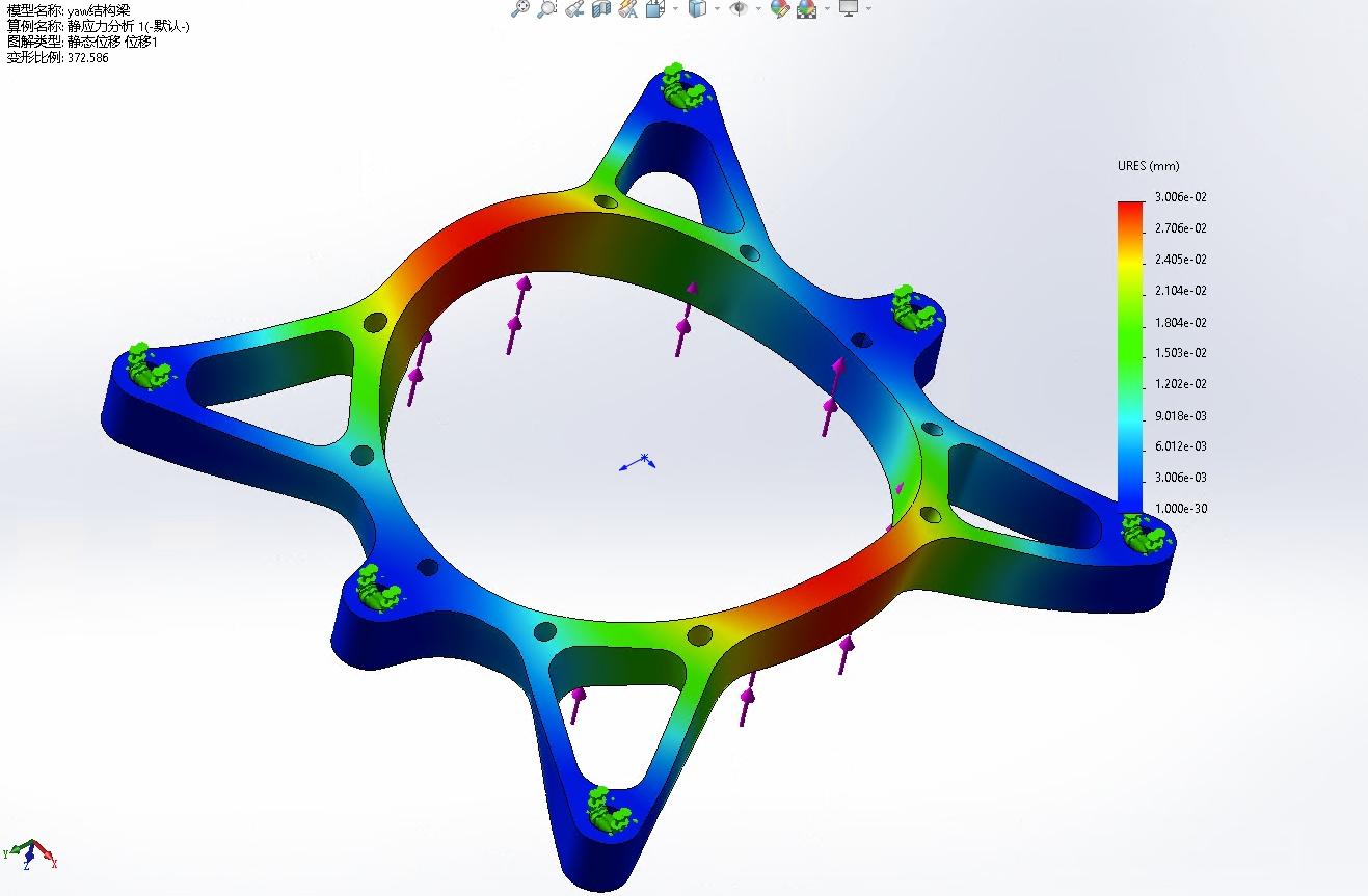
Deformation Simulation of YAW Axial Structure Beam
At the same time, Solidworks CAM is also used to simulate the manufacturing process of simulated parts, and the cutter path of CNC is simulated, which proves the feasibility of CNC manufacturing.
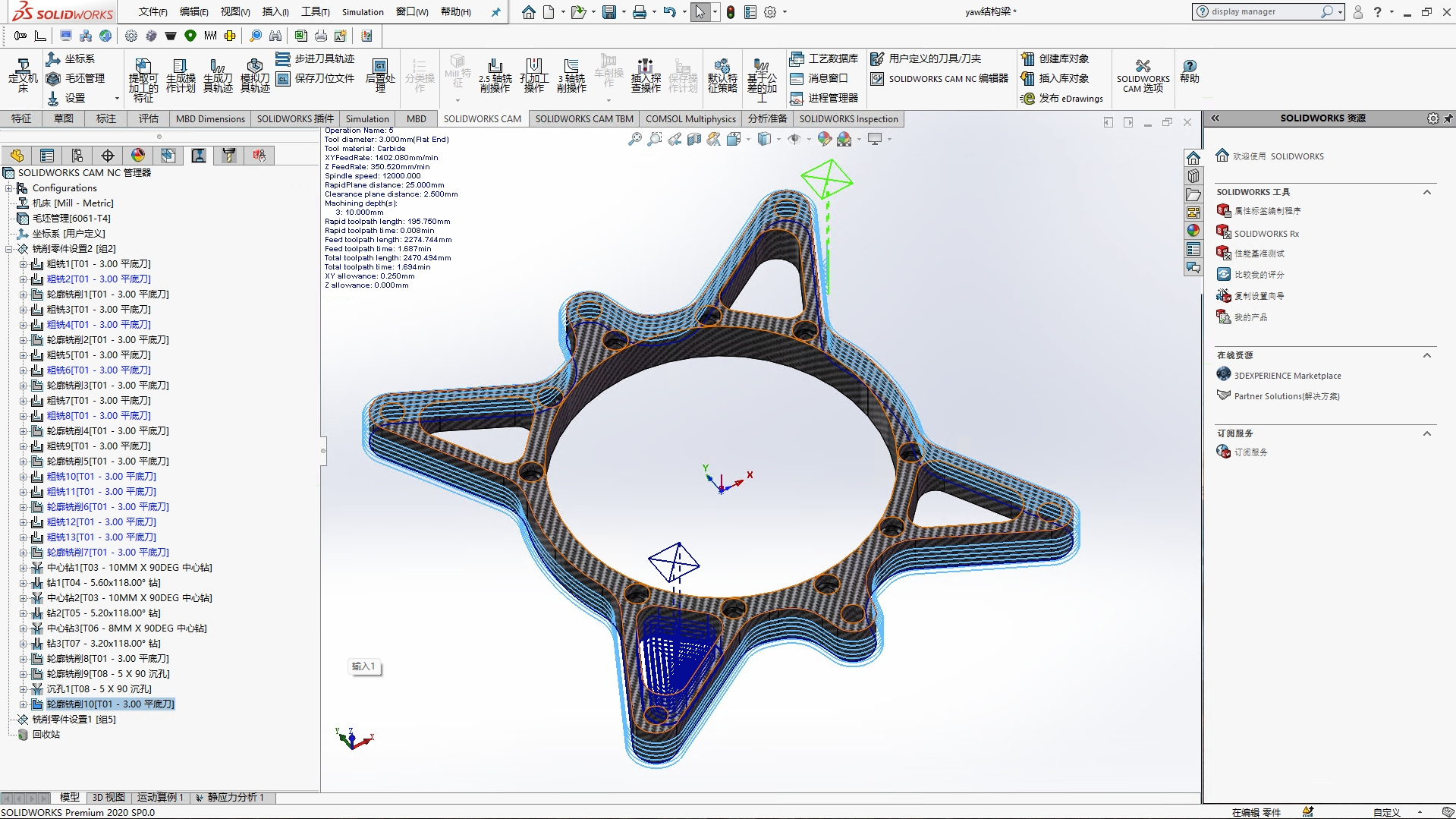
Simulation of CNC Tool Path of YAW Axial Beam
Sustainability Analysis
Environmental Feasibility Analysis
In combination with the manufacturing process of our gear, including: CNC carbon fiberboard engraving, CNC metal processing, metal additive manufacturing, and the use of some standard parts, we analyzed the environmental feasibility as follows:
-
Noise: These processes require the use of machines and equipment for operation and processing, which may generate relatively large noises, causing interference and effects on the surrounding environment and personnel.
-
Dust and Waste Gas: Metallic processing and metal additive manufacturing processes generate significant amounts of metal dust and waste gas, which may present a potential risk to the work environment and the health of personnel and require appropriate emissions and filtration.
-
Temperature and humidity: These processes also have certain requirements for ambient temperature and humidity, for example, metal additive manufacturing requires the use of laser to heat metal powder, and ambient temperature and humidity need to be controlled to ensure processing quality and accuracy.
-
Energy Consumption: These processes require significant amounts of energy for operation and processing and may have some impact on the environment without effective energy management and saving measures.
The environmental feasibility of these processes can be improved by taking appropriate control measures and supporting facilities, which should be assessed and optimized in combination with specific circumstances in practice. For example, soundproofing, venting, and filtering equipment may be used to reduce noise and emissions, or a more open environment may be selected for operation and processing.
Economic Feasibility Analysis In this project, the cost of the robot cloud platform we designed is mainly divided into four parts: CNC carbon fiberboard carving, metal additive manufacturing, CNC metal processing and standard parts.
There are a total of 6 CNC carbon fiberboard, including 1 piece with thickness of 1 mm, 2 pieces with thickness of 2 mm, 1 piece with thickness of 3 mm, 1 piece with thickness of 6 mm and 1 piece with thickness of 10 mm. All of them are single-sided engraving processing, with the processing cost of about 300 RMB.
Two gears using metal additive manufacturing process, in the future worksite processing website quote a total of 450 RMB.
A total of three parts using 6061 aluminum alloy CNC process, all can be processed using a triaxial machine tool. The processing cost is about 600 RMB.
The standard parts include electric sliding ring, motor, bearing, fastener, etc., with the total price of about 1400 RMB.
A total of 2,750 RMB was used, and this cost was within the acceptable range for competition robots.
Summary
Our group designed a Yaw Axis Gear for Gimbal of a hero robot applied in the Robomaster competition, which is characterized by: High accuracy: realize the accurate aiming target of robot head High reliability: Gimbal can operate stably for a long time, is not easy to damage, and has a long life span
-
High torque output: Allows the robot head to quickly adjust direction during the game
-
Low weight: Reducing robot weight helps improve robot motion flexibility
Our design features are:
Technologically, we chose the way of metal additive manufacturing, applied 316L stainless steel for metal 3D printing to manufacture stainless steel gears, and the other main parts were carved with carbon fiber CNC and CNC aluminum alloy. At the same time, we also plan to spray Teflon on the contact surface of gears, which can play a role in lubrication.